Choosing GPS-Guided Seeding Equipment: Accuracy and Compatibility
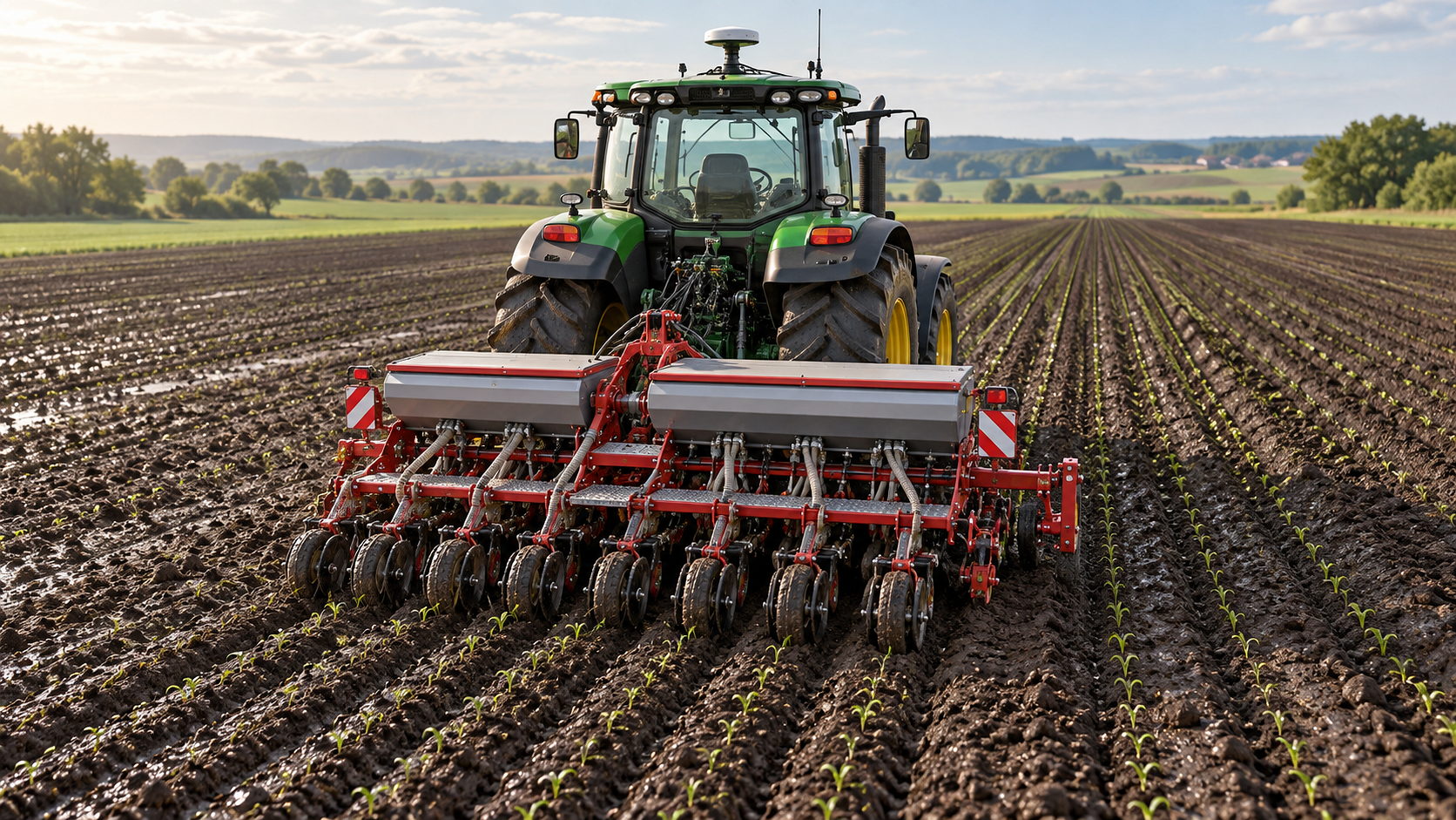




Choosing satellite-guided farming equipment for seeding starts with the placement tolerance the operation needs, then works backward through the positioning service, steering system and implement controls. A high-accuracy correction signal can be valuable for narrow row spacing, repeat passes or controlled traffic, but it will not compensate for an implement that drifts on slopes or a meter that delivers seed inconsistently.
For technical evaluators, the strongest candidate is therefore the configuration that can demonstrate acceptable row placement and repeatability in the intended fields, while working with the tractor, seeder and data systems already in use. That may be a fully integrated package or a retrofit. The distinction matters less than whether its components can exchange the necessary information and maintain performance throughout the planting window.
Define accuracy at the seed row
Positioning specifications often describe the estimated location of a receiver antenna. The operational requirement is usually different: the row must be placed where intended, with an acceptable relationship to neighboring rows or previous field passes. Between the antenna and the seed opener sit several sources of error, including steering response, tractor movement, hitch geometry, implement flex and lateral draft.
Separate the requirements before comparing correction services:
- Pass-to-pass accuracy: How closely adjacent passes must align during the same operation. This affects gaps and overlaps between seeded swaths.
- Repeatability: How closely the system must return to a previously used path after a longer interval. This matters when planting against established traffic lanes or returning to rows for later operations.
- Absolute position: How closely a recorded position corresponds to a geographic reference. This becomes important when field boundaries, guidance lines or prescription zones must align across machines and seasons.
- Seed placement within the row: Depth, spacing and seed-to-soil contact depend heavily on the planter or drill, its adjustment and field conditions. Satellite positioning alone does not guarantee them.
A quoted accuracy figure is useful only when its conditions are clear. Ask whether it represents pass-to-pass performance, repeatable position or receiver position under a defined statistical measure. Check the time interval, correction source and test conditions behind the claim. Two figures expressed in the same units may describe different outcomes.
For broad-acre drilling where modest overlap is acceptable, a lower-cost correction service may meet the requirement. A farm seeking to plant consistently beside permanent traffic lanes has a stronger reason to examine repeatability, steering response and implement movement together. In either case, the acceptable error should be set against row spacing, field layout and the cost of misplacement, rather than chosen solely from the smallest figure in a brochure.
Match the correction service to the field and the season
GNSS receivers use signals from satellite constellations to estimate position. Correction services improve that estimate, but they differ in how corrections are delivered, how long they take to converge, how repeatable positions are over time and what happens when corrections are interrupted.
Satellite-delivered correction services can be convenient where cellular coverage is weak, subject to service coverage and a clear view of the relevant satellites. Network RTK services generally depend on a communications link to receive corrections; coverage and reliability across the actual fields matter as much as a provider’s coverage map. A local RTK base station gives the operation more control over its correction source, but adds equipment, installation and maintenance responsibilities. Performance also depends on the base configuration and distance from it.
Compare services against the full planting workflow, not only the period when a machine is moving in an open field. Ask how long the receiver takes to reach its stated accuracy after startup or an interruption, whether the system warns the operator when accuracy degrades, and which functions continue when corrections are lost. Trees, terrain, structures, radio interference and connectivity gaps can all affect availability, although their impact depends on the equipment and location.
For repeat passes across seasons, establish how guidance lines are referenced and whether the same correction source and coordinate reference will be used. A change in base-station position, service, datum or configuration can shift the apparent location of saved lines. High pass-to-pass accuracy during one day does not by itself establish that those lines will be repeatable months later.
Evaluate the tractor and implement as one system
Steering compatibility is the first practical filter. Confirm that the guidance controller supports the tractor’s steering architecture and model, including any required hydraulic interface, steering valve, wheel-angle sensor or assisted-steering motor. A listed tractor family is a starting point; model year, factory preparation and software version can change what is needed.
Then trace the control path to the seeder. A display may be able to show a guidance line without controlling seed rate, sections or individual rows. Conversely, an existing implement controller may handle metering but be unable to share all coverage or prescription information with a replacement display. Identify which device owns each function, where the operator sets it and which screen reports a fault.
ISOBUS can simplify integration between compatible tractors, displays and implements, but the presence of an ISOBUS connector is not proof that every desired function will work. Compatibility depends on the devices, supported functions and software versions. Confirm separately whether the proposed combination supports the required implement interface, task management, prescription application, section control and documentation. Ask for a demonstration using the actual equipment configuration where possible.
Retrofits deserve particular scrutiny. A steering kit may fit the tractor while leaving an older drill with separate rate-control hardware, manual shutoffs or no means of reporting applied seed. That can still be a sensible purchase when the objective is guidance alone. It is a poor fit when the business case assumes automatic overlap control or reliable as-applied records that the implement cannot produce.
Account for implement movement
Even a tractor following its line accurately can pull a seeder away from the intended row. On side slopes, a trailing implement may move downhill; soil resistance, working depth and uneven draft can change its path as well. Long drawbars and wide implements can magnify the difference between tractor position and opener position, particularly during turns or on irregular terrain.
Basic setups estimate implement position from tractor location and configured offsets. That may be sufficient on level ground with stable draft. Where row alignment is more demanding, investigate implement-mounted positioning and whether the system supports passive monitoring or active implement steering. These are distinct capabilities: measuring implement position does not automatically provide a way to correct it.
Measure and enter antenna location, hitch points, implement width and offsets carefully, then calibrate according to the equipment supplier’s procedure. Also check the location used for section-control timing: a delay between the command and seed reaching the ground can leave gaps or overlaps at headlands even when the guidance line is accurate.
Check data compatibility before the purchase order
Data exchange should be tested in both directions. Import representative field boundaries, guidance lines and prescription files into the proposed display, then export coverage and application records to the software that will use them. A successful file transfer is only the first step: verify that the field appears in the correct location, the guidance line follows the intended path, units and rates are interpreted correctly, and recorded coverage matches the operation.
Ask which formats and transfer methods are supported by the specific display and software versions, including USB, wireless transfer or a connected platform where applicable. Determine whether moving data between brands requires conversion software or a paid service. Retain original files and define how names, field identifiers and versions will be managed when multiple machines work the same land.
Prescription seeding adds another layer of validation. The agronomic map, implement controller and meter must agree on the product, units, rate limits and location. Confirm how the system behaves outside a mapped area, when a prescription cannot be read or when the requested rate exceeds the implement’s operating range. A display showing a colored map does not establish that the meter is applying the intended rate.
Build the comparison around a field acceptance test
A practical evaluation puts each proposed configuration through the same representative tasks. Select fields that expose the conditions relevant to the operation: open ground, headlands, slopes, areas with potential signal obstruction and the tractor-seeder combinations expected to be used. Include the normal working speed and setup procedure; a result achieved only under unusually favorable conditions has limited purchasing value.
Agree on acceptance criteria before the demonstration. These can include allowable row-to-row deviation, overlap at headlands, recovery after a correction interruption, repeatability of a saved line and successful import and export of the required files. Specify how each result will be measured, how many passes or observations are needed and whether the implement is operating in the soil. Receiver diagnostics are useful, but they should be considered alongside measurements of the resulting rows or implement path.
Include the people who will set up and operate the system. Record the steps required to select the correct field, load a line or prescription, calibrate offsets and respond to a loss of correction. A configuration that meets the accuracy target but is difficult to set up consistently can introduce errors during a busy planting window.
Finally, compare the complete cost of each workable configuration: hardware, installation, unlocks, correction subscriptions, connectivity, data services, training and support. Define who is responsible for resolving problems across the tractor, guidance and implement suppliers. The preferred system is the one that meets the agreed field-level tolerance with a supportable integration and a cost proportionate to the operational benefit.
Related News
Agricultural Automation Still Needs Human Oversight, Study Finds
Agricultural automation still needs human oversight. Discover how AI and smart equipment are reshaping farm jobs, skills, and decisions.
Choosing a Precision Fertilization Equipment Manufacturer: What to Check
Choose a precision fertilization equipment manufacturer with confidence. Compare accuracy, compatibility, service and total ownership costs before you buy.
China's Autumn Grain Harvest Highlights Role of Machinery and Precision Farming
China's autumn grain harvest highlights machinery and precision farming. Explore how coordinated practices support harvesting and yield improvement.
Drip vs. Center Pivot Irrigation: Maintenance Tasks and Costs Compared
Use this irrigation solution comparison by maintenance to weigh drip vs. center pivot tasks, costs and downtime—and choose the best fit for your field.
EIMA 2026: Six Tractor of the Year Awards Include Autonomous Robot
Explore the Tractor of the Year awards at EIMA 2026, featuring six winners, including the AgXeed autonomous robot and leading tractor models.
Choosing Irrigation Systems for Government Projects: Water, Cost and Compliance
What factors affect irrigation system selection for government projects? Explore water supply, lifecycle costs and compliance to make a confident, well-informed choice.
Choosing an Agricultural Machinery Platform: Listings, Pricing, and Support
Choosing an agricultural machinery platform? Compare listings, pricing, supplier verification, and support to make a more confident equipment purchase.
Ofwat Launches £8 Million Agri-Water Innovation Challenge
Ofwat’s £8 million Agri-Water Innovation Challenge supports smart irrigation, water reuse and water-saving solutions. Explore the funding and its potential impact.
Choosing a Water-Saving Irrigation Supplier: 5 Key Procurement Criteria
Choose a water-saving irrigation systems supplier with confidence. Explore five procurement criteria to reduce risk and maximize long-term value.
Related News
- 00
0000-00
Choosing GPS-Guided Seeding Equipment: Accuracy and Compatibility - 00
0000-00
What to compare in integrated seeding combinations for heavy soils - 00
0000-00
When an integrated seeding combination improves field efficiency - 00
0000-00
How to Select a Heavy-Duty Seeder for Large Acreage and High-Residue Fields - 00
0000-00
How to Match Large-Scale Farm Equipment Working Width to Field Size and Crop Rows
0000-00
Popular Tags
Agri-Mechanization Fellow
Weekly Insights
Stay ahead with our curated technology reports delivered every Monday.