How agricultural equipment wireforms affect harness reliability in the field
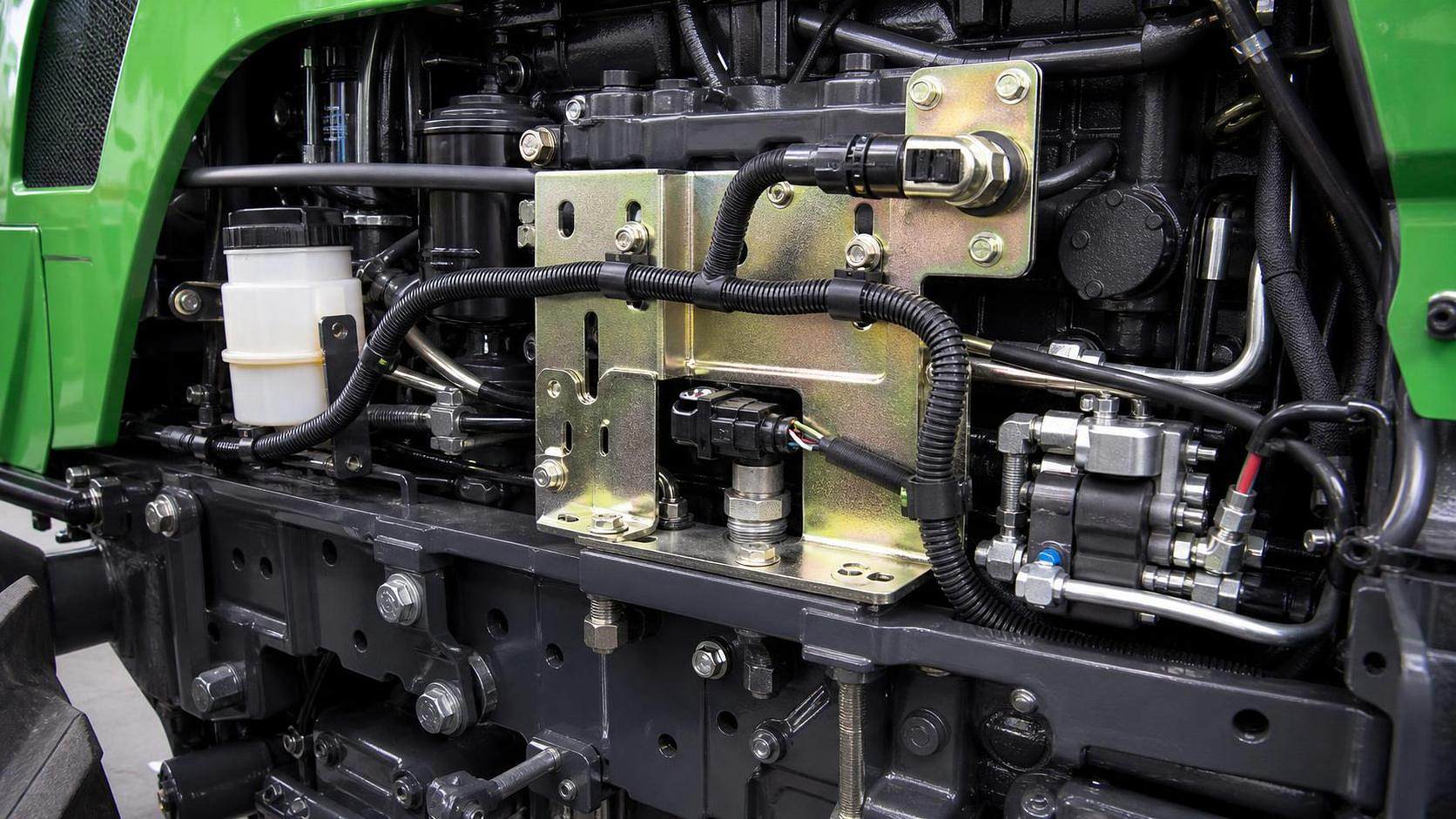




A harness can meet its electrical schematic, connector, and wire-gauge requirements yet still fail prematurely because its mechanical support system was under-specified. In tractors, combines, self-propelled sprayers, irrigation pumps, and implement-mounted control systems, agricultural equipment wireforms often determine whether a harness remains protected from vibration, abrasion, tensile loading, heat, and contamination throughout its service life.
The critical point is that a wireform is not merely a bent-metal retainer. Its geometry establishes the harness’s motion envelope; its material and coating determine how it survives corrosion; and its mounting position decides whether vibration is controlled or transferred directly into conductors and connectors. A low-cost clip or formed-wire support can therefore influence failure modes that may initially appear to be electrical faults: intermittent sensor signals, CAN communication errors, broken conductor strands near connectors, water ingress after connector movement, and insulation wear at chassis interfaces.
Harness reliability begins with controlled movement
Farm equipment does not expose wiring to one uniform vibration condition. The vibration spectrum changes with engine speed, ground speed, soil type, implement loading, harvesting mechanisms, hydraulic activity, and transport operation. A combine harvester adds cyclic excitation from threshing and cleaning systems. A tractor-mounted implement introduces relative movement between the tractor and attachment. Pivot irrigation systems may subject harnesses to repeated low-frequency motion, sunlight, moisture, and cable flexing over long spans.
Wireforms affect reliability by controlling where a harness is allowed to move and where it must remain stationary. This distinction matters because unrestricted harness movement creates repeated contact with surrounding structure. Once the outer jacket begins to wear, the remaining failure path may be short: insulation damage, conductor exposure, moisture ingress, corrosion, or a short-to-ground event.
A properly designed support does not immobilize every section of cable. Excessive restraint can be as damaging as inadequate restraint. When a harness is clamped too rigidly between moving structures, thermal expansion, chassis flex, engine motion, or articulation loads are redirected into the wire bundle and connector terminations. The design objective is controlled retention: enough support to prevent chafing and excessive displacement, with enough compliant length and bend allowance to avoid transferring force into conductors.
This is why clip spacing cannot be specified solely by a generic distance rule. The required spacing depends on bundle mass, unsupported span, vibration amplitude, mounting orientation, local temperature, expected mud accumulation, and whether the harness is routed beside a moving hydraulic line, sharp sheet-metal edge, rotating assembly, or heat source. A short unsupported section near a connector can be more consequential than a much longer span in a protected, low-vibration enclosure.
Wireform geometry determines where stresses accumulate
The shape of a wireform controls contact pressure, cable retention, assembly access, and the radius imposed on the harness. Small geometric details have disproportionate effects in field conditions.
An open-loop or spring-style wireform can make installation and service easier, but it must retain the harness under vibration without pinching its jacket. A support that closes too tightly may create a localized pressure point. Over time, vibration turns that point into a wear interface, especially when grit, crop residue, or dried soil enters the contact area. Conversely, a wireform with excessive clearance allows the bundle to rattle, changing the support from a restraint into an abrasive guide.
Edges deserve particular scrutiny. Cut ends, weld flash, burrs, incomplete coating coverage, and tight internal radii can damage corrugated conduit, braided sleeving, tape wraps, and unprotected cable jackets. The risk is higher where the harness enters or exits the wireform at an angle. Although the contact point may appear benign when stationary, operating vibration can cause the bundle to saw repeatedly against a small area of metal.
Wireform geometry should also be evaluated as part of the complete retention stack, not as an isolated component. A harness may include conduit, tie wraps, edge protection, grommets, secondary clips, and connector backshells. If the wireform retains only the conduit while allowing the underlying cable bundle to migrate, the apparent support can conceal internal movement. If a tie wrap is used within a metal wireform, its tail orientation and locking-head location must not become another abrasion source.
At pivot points, hood hinges, cab-to-chassis transitions, folding booms, steering joints, and implement interfaces, the wireform must preserve a predictable bend path. The relevant question is not whether the harness fits when assembled; it is whether it retains an acceptable bend radius through the full range of movement, including vibration superimposed on normal articulation.
Material selection is a corrosion and fatigue decision
Carbon steel wireforms can provide adequate strength and cost efficiency in sheltered locations, but agricultural machinery frequently operates in conditions that challenge protective finishes: fertilizer residues, wet soil, road de-icing salts, irrigation water, livestock environments, and long periods of outdoor storage. Once corrosion begins at a wireform, its effect is not limited to the support itself. Rust expansion can crack coatings, create rough contact surfaces, reduce spring retention, and trap moisture against the harness.
Stainless steel generally offers improved corrosion resistance, but “stainless” is not a complete specification. Grade selection must reflect the exposure environment, crevice conditions, chloride exposure, and the material of the mounting structure. A stainless wireform attached directly to a dissimilar metal bracket can create galvanic-corrosion concerns if the joint remains wet and electrically conductive. Isolation washers, compatible coatings, drainage, and mounting design may be necessary where material combinations create an unfavorable corrosion couple.
Spring properties are equally important. A wireform that relies on elastic force to retain conduit or cable must maintain that force after repeated opening, thermal cycling, and vibration. Material hardness, wire diameter, bend radius, heat treatment, and forming process all influence fatigue behavior. An apparently robust form can lose retention if its design repeatedly drives the wire beyond its intended elastic range during installation or service.
For locations exposed to hydraulic oil, diesel fuel, urea solution, fertilizer, cleaning chemicals, or UV radiation, the wireform cannot be assessed independently from adjacent polymer components. A durable metal support may still become part of a failure mechanism if its coating degrades, sheds particles, or interacts poorly with a conduit, rubber grommet, or cable jacket selected for the same location.
Coatings are functional surfaces, not cosmetic finishes
Zinc plating, zinc-rich systems, organic coatings, powder coatings, and polymer-dipped finishes can all be used on formed-wire supports, but they do not provide equivalent protection in every installation. The most relevant questions are where the coating can be damaged, whether the wireform has crevices that retain moisture, and whether the surface remains smooth after exposure and assembly.
A coating that performs well on an exposed flat bracket may be less reliable on a tight-radius wireform, at welded zones, or under repeated harness contact. A hard coating can resist general corrosion but may become abrasive if it chips. A softer polymer coating can reduce jacket wear, yet it must resist cracking, swelling, peeling, and UV degradation in the intended environment. Coated wireforms should therefore be checked after representative assembly operations, not only in an as-received condition.
Mounting holes and fasteners need equal attention. If the wireform is protected but the fastener interface corrodes, loss of clamp load or structural loosening can reintroduce movement. Drainage orientation matters as well. A downward-facing opening may shed water and debris, whereas a cup-shaped feature can hold mud and moisture against both the support and the harness.
Connector fatigue often originates upstream of the connector
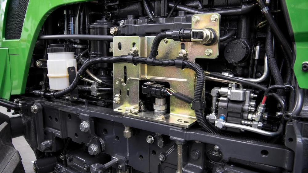
Electrical connectors are commonly investigated when an intermittent fault appears, but wireform placement often decides whether a connector experiences repeated bending load. A harness should not hang from a connector, and the first support point should be positioned to prevent the connector termination area from becoming the primary flex point. At the same time, placing a rigid support immediately adjacent to the connector can create a sharp transition from fixed harness to flexible lead, concentrating bending in a narrow section.
The more reliable arrangement is a managed strain-relief zone: the connector is protected from direct load, the harness has sufficient service loop or controlled flex length, and the first retention point prevents large-amplitude motion without creating a hard hinge. The optimum distance is application-specific because it depends on conductor size, bundle stiffness, connector construction, expected relative movement, and available space.
This principle is especially relevant for sensors on engines, transmissions, hydraulic valves, grain-loss monitors, level sensors, and implement electronics. These locations often combine heat, vibration, fluid exposure, and limited access. A wireform that makes connector removal difficult can encourage improper service practices, including pulling on wires, cutting tie wraps without replacing retention, or rerouting the harness outside its intended protected path.
Installation design must account for maintenance, contamination, and assembly variation
Wireforms are frequently specified from nominal CAD geometry, while their real performance depends on assembly tolerances and field service conditions. A harness with one additional protective sleeve, a different conduit wall thickness, or a revised branch breakout can fit differently in the same support. If retention depends on a narrow tolerance window, production variation can result in either loose routing or installation force high enough to damage the harness.
Service access should be treated as a reliability variable. A wireform that requires excessive force, special tool access, or awkward hand position may be omitted or improperly reinstalled after maintenance. Designs that clearly indicate the intended harness path and allow controlled removal reduce this risk. Where repeated service is expected, the retention feature should tolerate multiple open-close cycles without loss of holding force or damage to its protective surface.
Contamination changes fit and contact behavior. Crop residue and mud can accumulate in open forms; fine dust can act as an abrasive; frozen debris can prevent complete seating; and wet organic material can keep a corrosion-prone interface damp. A support located in a high-debris zone may need a geometry that sheds material rather than captures it. In some cases, moving the wireform a short distance to a cleaner structural member provides a greater durability benefit than changing its base material.
How applicable standards should be used
No single agricultural-equipment standard functions as a universal wireform specification. The component should instead be verified within the environmental, electrical, mechanical, and machine-level requirements applicable to the vehicle or system.
For electrical and electronic equipment exposed to vehicle environments, ISO 16750 is often used as a reference framework for environmental conditions and testing concepts, including vibration, mechanical shock, temperature, chemical exposure, and climatic loads. Its scope is road vehicles, so it should not be treated as automatic proof of suitability for agricultural machinery. It can nevertheless help structure an environmental verification plan where equivalent machine-specific requirements are not already defined.
ISO 14982 addresses electromagnetic compatibility of agricultural and forestry machines. Wireforms do not themselves establish EMC compliance, but poor harness retention can alter routing, shielding continuity, separation from high-current cables, and connector integrity. Mechanical routing changes can therefore create secondary EMC consequences, particularly around sensor networks and electronically controlled hydraulic systems.
Where functional safety-related control systems are involved, ISO 25119 provides a framework for safety-related parts of control systems on agricultural and forestry machinery. The practical implication for wireform evaluation is straightforward: a support failure that can cause loss of power, sensor signal interruption, unintended wire damage, or degraded diagnostic capability should be considered in the system’s fault analysis rather than dismissed as a non-critical mechanical detail.
Internal specifications should define the measurable attributes that these broader standards do not prescribe: material grade, wire diameter, coating system, allowable burr condition, minimum edge radius, retention force range, mounting torque, bundle diameter range, corrosion exposure method, and vibration test configuration. A retention-force requirement without an accompanying vibration and wear assessment is incomplete, because a clip can hold securely in a static pull test while damaging the harness during cyclic motion.
Evaluation should focus on failure mechanisms, not catalog descriptions
A technically useful review starts at the installation location. Identify the local vibration source, temperature range, contaminants, relative movement, adjacent surfaces, service actions, and consequence of harness failure. Then assess the wireform as part of a route rather than as a standalone purchased item.
Particular attention is warranted where a harness crosses a structural edge, exits a protected enclosure, approaches an engine or exhaust-adjacent zone, follows hydraulic plumbing, or transitions between fixed and moving assemblies. These are locations where nominally adequate supports can become inadequate after machine flex, clamp relaxation, conduit wear, or changes in harness mass caused by accumulated contamination.
The most dependable agricultural equipment wireforms are not necessarily the heaviest or most rigid. They are the forms that maintain a smooth, corrosion-resistant, correctly positioned interface between the harness and the machine structure while allowing the intended motion and service access. Evaluating that interface under realistic movement, environmental exposure, and assembly conditions is what turns a bent-metal component into a reliable part of the electrical system.
Related News

How to Evaluate Agricultural Product Information Sources for Reliable Farm Decisions
Agricultural product information reference guide: evaluate reliable farm data, verify claims, and make smarter machinery, irrigation, and crop decisions.

Farm Machinery Guide: Matching Tractor Horsepower and Implements to Farm Size
Farm machinery guide for tractors: match horsepower, implement width, hydraulics, traction, and fleet capacity to farm size for lower costs and reliable field performance.
How to Evaluate Drip Irrigation System Manufacturers for Large Farm Projects
Drip irrigation systems manufacturer evaluation guide for large farms: compare hydraulic design, filtration, quality control, scalability, delivery, and support.
Specification Planning: A Practical Framework for Defining Equipment Requirements
Application guidance for specification planning: define measurable equipment requirements, prioritize performance, and avoid costly procurement mistakes.

How North American Farms Can Select Crop Monitoring Systems by Acreage and Connectivity
Crop monitoring systems North America: learn how to match acreage, connectivity, sensors, and data workflows for reliable, actionable farm decisions.

Where to Find Reliable Product Information for Comparing Farm Equipment
Product information resources agriculture buyers can trust: compare farm equipment with technical specs, manuals, field data, dealer support, and lifecycle insights.
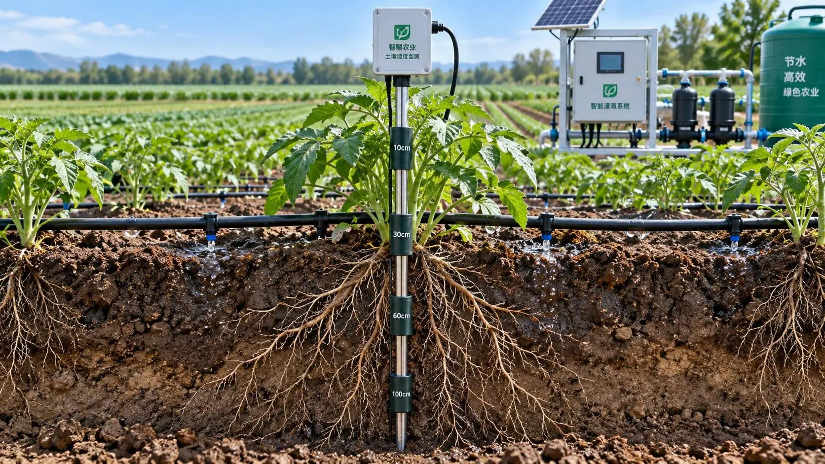
Selecting Real-Time Soil Moisture Sensors for Irrigation Zone Control
Soil moisture sensors real time: learn how to select reliable probes, optimize zone control, improve irrigation decisions, and scale precision water management.
Tractor Hydraulic Systems Troubleshooting: Diagnosing Weak Lift and Slow Implements
Tractor hydraulic systems troubleshooting made practical: diagnose weak lifts and slow implements with proven pressure, flow, valve, and oil-supply checks.
How Tractor Intelligence Systems Improve Field Efficiency and Input Accuracy
Agricultural machinery intelligence for tractors improves field efficiency, input accuracy, data traceability, and implement control. Explore smarter evaluation strategies.
Related News
- 00
0000-00
How to Evaluate Agricultural Product Information Sources for Reliable Farm Decisions - 00
0000-00
Farm Machinery Guide: Matching Tractor Horsepower and Implements to Farm Size - 00
0000-00
Specification Planning: A Practical Framework for Defining Equipment Requirements - 00
0000-00
Where to Find Reliable Product Information for Comparing Farm Equipment - 00
0000-00
How to Evaluate Crop Monitoring System Manufacturers for Large-Scale Farms
Popular Tags
Ms. Elena Rodriguez
Weekly Insights
Stay ahead with our curated technology reports delivered every Monday.