
Smart Irrigation Equipment for Drip Systems: Key Compatibility Checks
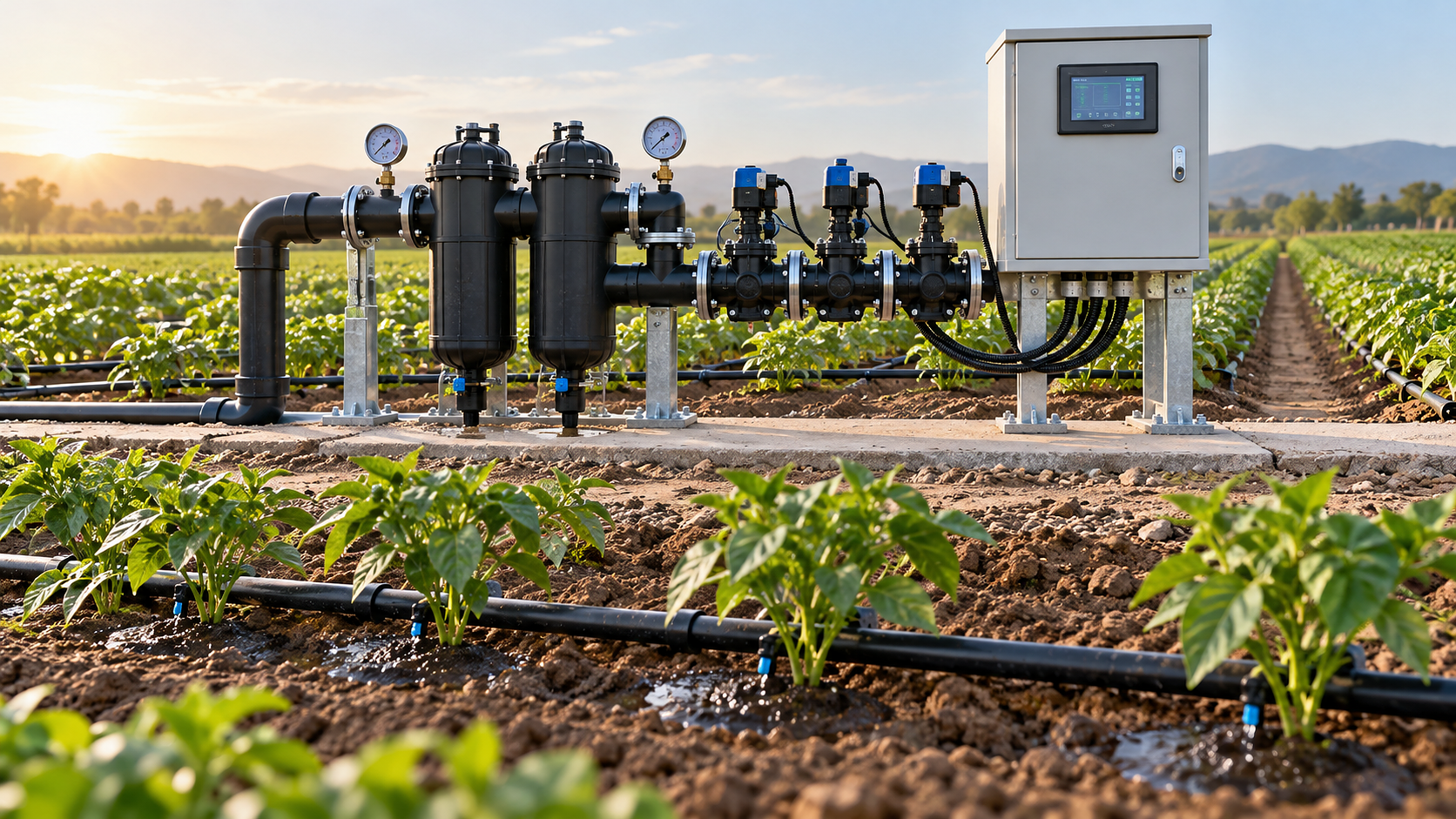




Select smart irrigation equipment only after confirming that it can operate within the existing drip system’s hydraulic limits, actuate its valves reliably, and exchange usable data with its sensors and control software. A controller with advanced scheduling cannot correct inadequate pressure at the end of a lateral, and a compatible radio connection does not establish compatibility between control commands.
Start with the conditions the upgrade must support: the smallest irrigation zone, the largest permitted combination of zones, elevation changes, water quality, available power, and expected connectivity interruptions. These conditions expose mismatches that individual product specifications often conceal.
Establish the hydraulic operating envelope first
Record pressure and flow while irrigation is running. Static pressure at the pump or supply connection gives little indication of what remains available after water passes through filters, valves, regulators, submains, and laterals. Measurements should include representative high and low elevations and the hydraulically disadvantaged ends of the network.
The required supply pressure must cover the emitter operating requirement, elevation effects, and losses through the entire active flow path. Filter losses increase as contaminants accumulate, so a design that works immediately after cleaning can become unreliable before the next backwash. Where pressure regulation is installed, allow for the regulator’s required inlet-to-outlet differential.
Pressure-compensating emitters maintain their intended discharge only within their specified operating range. Below that range, compensation no longer delivers the expected uniformity. Above the allowable pressure, tubing, fittings, and emitters face excessive stress. Automation therefore needs pressure limits derived from the installed components, rather than a generic “drip irrigation” setting.
Flow compatibility needs equal attention. Estimate zone demand from emitter discharge and emitter count, then compare it with measured flow. Existing clogging, leaks, or undocumented lateral changes can make the original design schedule misleading. Evaluate both maximum simultaneous demand and the smallest zone: a flow meter, control valve, or variable-speed pump sized for peak demand may perform poorly at low flow.
Match valves, electrical outputs, and switching behavior
A controller output must match the valve actuator’s electrical requirements. Conventional AC solenoids, DC latching solenoids, and motorized valves require different drive arrangements. A matching nominal voltage alone does not establish compatibility; current capacity, switching waveform, polarity requirements, and output duration also matter.
For conventional solenoids, account for starting current as well as holding current. Long cable runs introduce voltage drop, especially when several valves energize together. DC latching valves require the correct pulse characteristics and polarity reversal. A replacement controller that assumes continuously energized valves will not directly operate them.
Hydraulic valve sizing deserves separate review. Pilot-operated diaphragm valves have operating requirements that include pressure differential and, for some designs, minimum flow. An oversized valve serving a small drip zone can behave unpredictably even when its solenoid is electrically compatible.
Sequence timing also affects compatibility. Opening several zones simultaneously can collapse pressure; closing them rapidly can create transients. Confirm that the controller supports the required valve delays, pump start sequence, and controlled shutdown. Pump outputs generally operate through suitable control equipment rather than directly powering the motor.
Include filtration, flushing, and fertigation in the control logic
Emitter filtration requirements should come from the emitter documentation and water analysis. Mesh numbers alone are an unreliable basis for comparing filtration products across different constructions. Compare the stated particle retention size and filtration characteristics, together with performance at the intended flow.
Pressure measurements upstream and downstream of a filter reveal loading only when interpreted against operating flow. A larger pressure difference during a higher-flow irrigation cycle does not automatically indicate increased contamination. Automatic backwashing also needs sufficient pressure and flow, which must remain available during the permitted operating sequence.
Flushing creates a different hydraulic condition from normal irrigation. Opening lateral ends or automatic flush valves increases demand and changes the expected flow signature. The controller must recognize this state so that leak protection does not interrupt a planned flush. Conversely, a flush valve stuck open should not remain hidden behind an indefinitely suppressed alarm.
Where fertigation is installed, verify material compatibility with the actual chemicals, concentrations, and temperatures at the point of contact. Injection should be interlocked with confirmed water flow, with a defined response to pump failure or zone shutdown. Include backflow protection and the required clean-water flushing sequence in the integration design; an available dosing output does not establish that these safeguards exist.
Verify the full sensor measurement chain
Sensor compatibility has three layers: the physical connection, the meaning of the signal, and the suitability of the measurement. A controller might accept an analog input while lacking the excitation supply, input characteristics, or scaling needed by a particular transmitter. Pulse inputs likewise have limits for frequency, pulse width, and electrical signal type.
For each measurement, document the engineering unit, measurement range, calibration method, sampling interval, and treatment of invalid readings. A pressure signal interpreted with the wrong range can look plausible while shifting every alarm threshold. Flow meters need installation conditions that suit their measurement principle, including pipe filling and any specified straight lengths or orientation.
Soil sensors introduce an additional interpretation problem. Volumetric water content, soil water tension, and electrical conductivity describe different properties. Their values cannot be substituted within a scheduling rule simply because all devices are described as soil sensors. Soil texture, salinity, temperature response, installation contact, and calibration affect how readings support irrigation decisions.
Placement must reflect drip wetting patterns. A sensor directly beneath an emitter can register rapid wetting while substantial root-zone soil remains dry. A sensor beyond the wetted volume can suggest persistent water shortage. Define placement relative to emitters, active roots, and soil layers before comparing control algorithms.
For any sensor-driven shutdown, define what happens when data becomes stale, disappears, or exceeds a credible range. Distinguish a real dry-soil condition from a disconnected probe. Continued irrigation using a bounded fallback schedule and immediate shutdown have different consequences; the appropriate response depends on the fault and the hydraulic safeguards available.
Separate network connectivity from functional interoperability
Shared communication labels establish only part of an interface. RS-485 identifies an electrical communication layer, while Modbus implementations still require matching device settings, register definitions, data types, and scaling. MQTT requires agreement on topics, payloads, authentication, and message handling. Devices sharing a radio technology can still depend on incompatible gateways or application formats.
Request an interface description that shows the actual operations supported: reading measurements, changing schedules, issuing valve commands, retrieving alarms, and confirming execution. A system that exports sensor readings but accepts no external commands provides a different integration path from one offering documented control access.
Command acknowledgment needs careful interpretation. Receipt by a cloud service does not prove that a field valve opened. Stronger confirmation links the command to a local output state and, where available, measured pressure or flow. This distinction matters when diagnosing communication delays, actuator faults, and hydraulic failures.
Evaluate coverage at the installed antenna positions with enclosures closed and representative crop conditions. Wet vegetation, terrain, metal cabinets, and antenna placement influence radio performance. Battery-life estimates also depend on reporting frequency, retries, and signal conditions; frequent control exchanges impose different demands from occasional monitoring.
Where several systems can change a schedule, define control authority. Local programming, cloud scheduling, and external software must have explicit precedence so that an older instruction does not overwrite a field adjustment. Time zones, clock synchronization, and daylight-saving behavior also need consistent handling across logs and scheduled events.
Make offline behavior and fault responses observable
Determine which functions run locally and which require an internet connection. Cached schedules, local sensor rules, valve sequencing, and pump interlocks should be evaluated individually. A gateway that stores data during an outage might still depend on the cloud to make irrigation decisions.
Power loss creates separate questions. A latching valve can retain its previous state after controller power disappears, while other actuator arrangements behave differently. Recovery must account for actual valve position, pump status, and interrupted irrigation events. Automatically repeating a complete cycle after restoration could overwater a zone that had nearly finished.
Alarm logic should use the expected behavior of each zone. High flow can indicate a broken lateral, an open flush path, or an unintended valve opening. Low flow can result from clogging, a partly closed valve, inadequate supply, or a measurement problem. Pressure and flow together provide better fault discrimination than either signal alone.
Allow a defined stabilization period after switching, then apply thresholds appropriate to the active zone configuration. Excessive delay conceals faults; immediate evaluation during filling produces nuisance alarms. Retained event records should connect commands, measurements, communication status, and alarm actions so that a fault can be reconstructed.
Use a field acceptance test to resolve remaining uncertainty
Before testing, assemble a compact compatibility record containing component models, firmware versions, wiring details, hydraulic limits, interface mappings, and required control behavior. Mark any unverified interface explicitly. Claims such as “supports external sensors” need resolution to a particular sensor model and configuration.
Acceptance testing should cover the operating conditions most likely to expose a mismatch:
- Run the smallest zone and the highest-demand permitted combination, recording flow and pressure at relevant field points.
- Exercise filter backwashing and lateral flushing, including their interaction with pump control and flow alarms.
- Interrupt communications during an active cycle. Observe local operation, queued commands, and recovery after reconnection.
- Disconnect a critical sensor, simulate an implausible reading where the equipment permits it, and verify the intended fallback.
- Test power restoration and an unsuccessful valve command. Confirm that displayed status distinguishes a requested action from a verified hydraulic response.
Set pass criteria before the trial using emitter limits, pump requirements, actuator specifications, and the intended irrigation rules. Retain the configuration and event logs that produced the result. Approval can then rest on demonstrated operation across the required conditions, with any remaining integration work identified before installation expands.
Related News
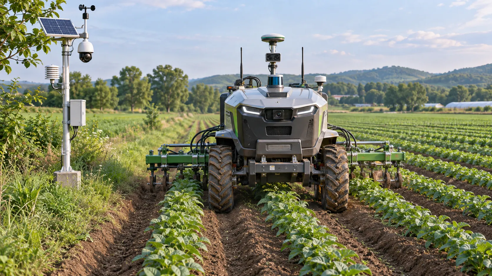
Agricultural Automation Still Needs Human Oversight, Study Finds
Agricultural automation still needs human oversight. Discover how AI and smart equipment are reshaping farm jobs, skills, and decisions.
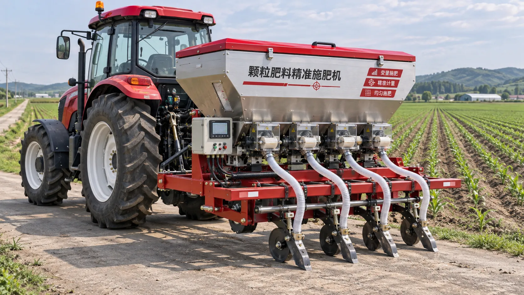
Choosing a Precision Fertilization Equipment Manufacturer: What to Check
Choose a precision fertilization equipment manufacturer with confidence. Compare accuracy, compatibility, service and total ownership costs before you buy.
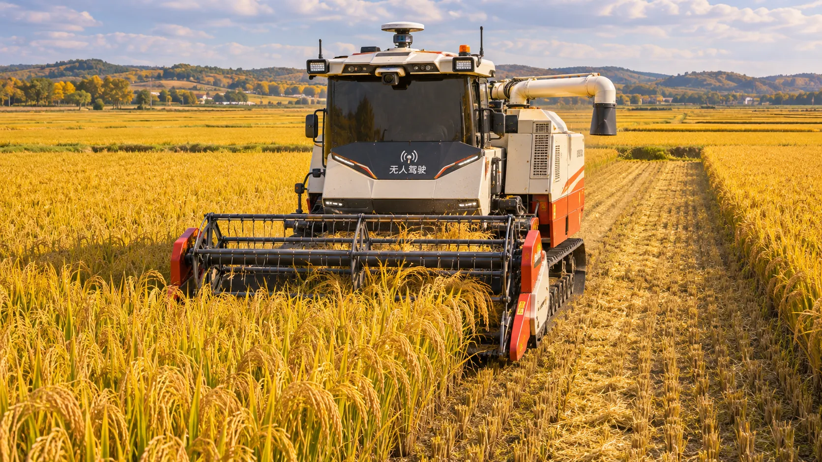
China's Autumn Grain Harvest Highlights Role of Machinery and Precision Farming
China's autumn grain harvest highlights machinery and precision farming. Explore how coordinated practices support harvesting and yield improvement.
Drip vs. Center Pivot Irrigation: Maintenance Tasks and Costs Compared
Use this irrigation solution comparison by maintenance to weigh drip vs. center pivot tasks, costs and downtime—and choose the best fit for your field.
EIMA 2026: Six Tractor of the Year Awards Include Autonomous Robot
Explore the Tractor of the Year awards at EIMA 2026, featuring six winners, including the AgXeed autonomous robot and leading tractor models.
Choosing Irrigation Systems for Government Projects: Water, Cost and Compliance
What factors affect irrigation system selection for government projects? Explore water supply, lifecycle costs and compliance to make a confident, well-informed choice.
Choosing an Agricultural Machinery Platform: Listings, Pricing, and Support
Choosing an agricultural machinery platform? Compare listings, pricing, supplier verification, and support to make a more confident equipment purchase.
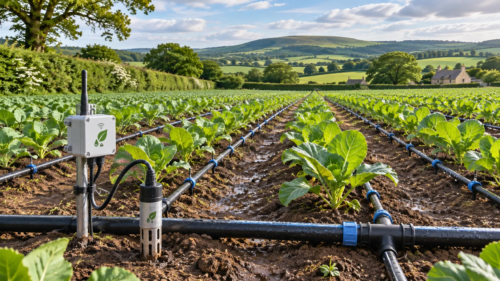
Ofwat Launches £8 Million Agri-Water Innovation Challenge
Ofwat’s £8 million Agri-Water Innovation Challenge supports smart irrigation, water reuse and water-saving solutions. Explore the funding and its potential impact.
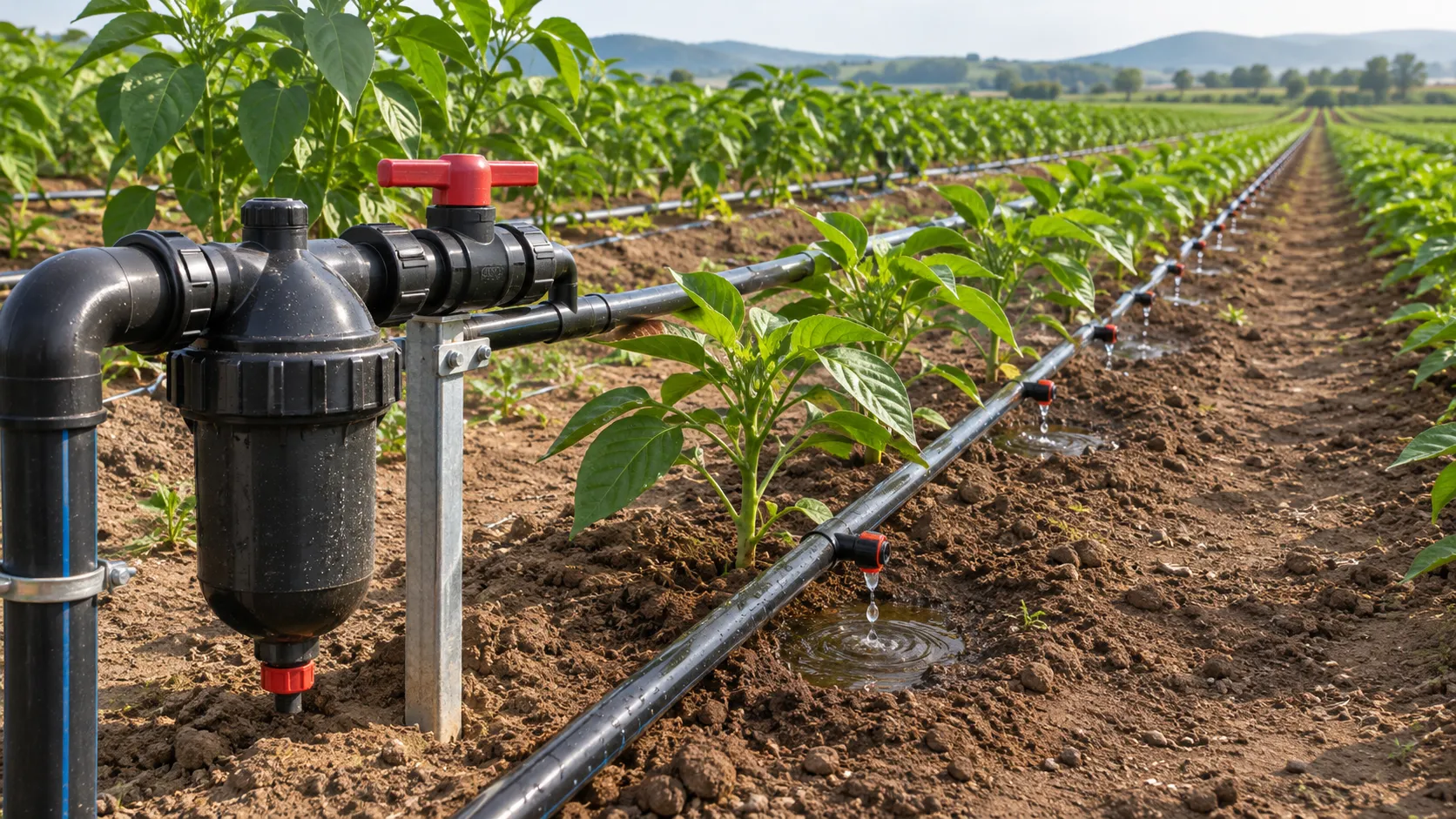
Choosing a Water-Saving Irrigation Supplier: 5 Key Procurement Criteria
Choose a water-saving irrigation systems supplier with confidence. Explore five procurement criteria to reduce risk and maximize long-term value.
Related News
- 00
0000-00
Drip vs. Center Pivot Irrigation: Which Saves More Water for Your Farm? - 00
0000-00
Low-Pressure Drip Irrigation: Choosing Emitters to Save Water and Maintain Uniformity - 00
0000-00
Choosing Smart Irrigation Equipment for Orchards With Existing Drip Systems - 00
0000-00
Smart Irrigation Equipment for Drip Systems: Key Compatibility Checks - 00
0000-00
Choosing Drip Irrigation Systems for Open Fields: Soil, Slope, and Water Quality
0000-00
Popular Tags
Hydrological Resource Strategist
Weekly Insights
Stay ahead with our curated technology reports delivered every Monday.