Low-Pressure Drip Irrigation: How to Fix Uneven Watering Without Raising Pressure
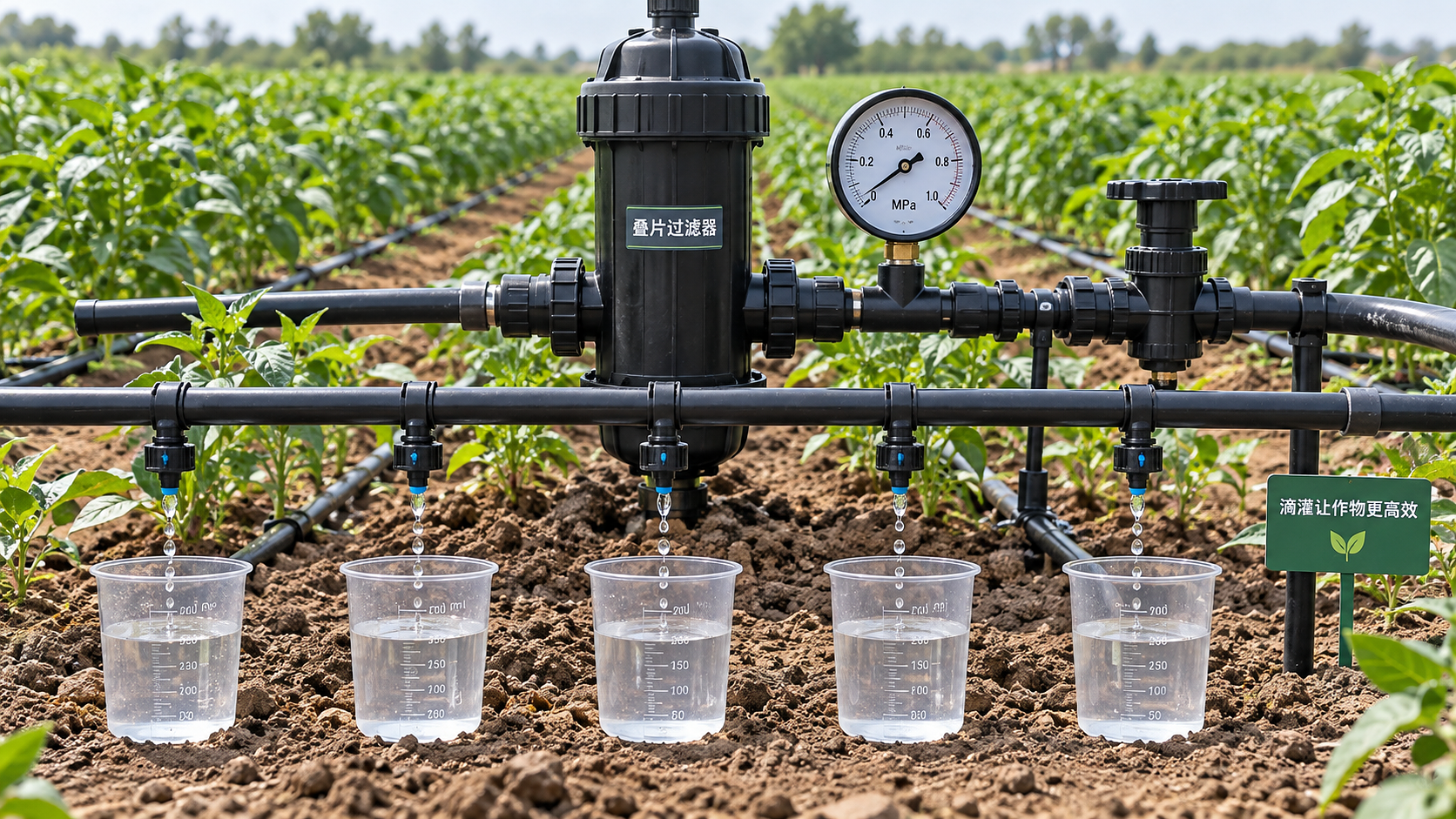




Uneven drip irrigation does not automatically mean the supply pressure is too low. A dirty filter, partially closed valve, leaking connection, blocked emitter, or overloaded lateral can leave part of a field dry while the inlet gauge appears normal. Raising pressure may temporarily hide the fault, increase discharge near the supply, or exceed the limits of drip tape and fittings.
The effective correction is to identify where pressure or flow becomes uneven, then remove that cause. There is one important limit: every emitter needs sufficient operating pressure. If the available pressure is below its specified range, maintenance alone cannot restore rated performance. The remedy must reduce hydraulic losses, change the layout, or use emitters suited to the available head—not simply extend irrigation time.
Confirm that uneven soil wetting means uneven emitter discharge
Different wetting patterns do not necessarily indicate a hydraulic fault. Sandy soil produces a narrower, deeper wetted zone than finer-textured soil. Compaction, slope, mulch, and emitter placement also affect the visible pattern. Before changing equipment, measure water leaving the emitters.
With the affected zone operating normally, collect discharge from selected emitters for the same measured interval. Include laterals near, midway along, and far from the zone inlet, with samples at the beginning, middle, and end of those laterals. Include high and low ground rather than sampling only convenient locations.
Use identical collection methods without squeezing tubing, disturbing outlets, or adding backpressure. Allow the system to fill and stabilize before timing. For anti-drain emitters, confirm that their opening pressure has been reached; startup delay is not the same as steady-state under-delivery.
Convert collected volume to discharge:
Flow in liters per hour = collected milliliters × 3.6 ÷ collection time in seconds.
For example, 100 milliliters collected in 180 seconds equals 2 liters per hour. This is a calculation example, not a performance target; compare results with the installed emitter’s specifications.
If measured discharge is reasonably consistent but soil wetting differs, investigate soil conditions, placement, and scheduling. Hydraulic alterations will not correct differences in soil infiltration.
Read pressure and discharge together
Measure pressure while the zone is running, not only with valves closed. Static pressure can look adequate even when a restriction or excessive demand causes operating pressure to collapse. Use a gauge with a range and resolution appropriate for low-pressure service; small differences may be invisible on a high-range gauge.
Record pressure upstream and downstream of the filter, at the zone inlet, and at representative lateral inlets and ends. Take readings under comparable operating conditions. Where supply pressure fluctuates, simultaneous readings are more reliable than measurements taken several minutes apart.
These patterns guide investigation; they are not proof by themselves. A lateral can have both sediment accumulation and excessive friction loss. Change one condition at a time and repeat the measurements so that improvement can be attributed to a specific correction.
Recover pressure lost before it reaches the emitters
In low pressure water-saving irrigation systems, avoidable losses can consume a significant share of the available operating head. Start with components that can be restored without redesigning the field.
Check filters without bypassing protection
Inspect screens, discs, seals, and backwash operation according to the filter design. Compare pressure differential under flow with the manufacturer’s cleaning threshold rather than applying a universal value. A low differential does not prove the filter is sound: a damaged or incorrectly seated element can pass contaminants without creating much resistance.
Do not remove filtration or substitute a coarser element merely to recover pressure. Filtration must match the emitter requirement and water quality. Otherwise, an apparent pressure improvement can become widespread emitter blockage.
If the cleaned filter still causes excessive loss at the required flow, inspect connecting pipework and assess filter capacity. A larger suitable filtration area can reduce loss while retaining the required filtration grade.
Inspect valves, regulators, and leaks under operating conditions
Check for partly closed valves, debris in valve seats, undersized fittings, kinked tubing, and crushed hose. A pressure regulator also needs sufficient inlet pressure and an appropriate flow range. A regulator selected for higher-pressure service may not control properly when the available supply barely meets its outlet setting.
Verify performance against its published operating requirements. Do not remove regulation without checking maximum supply pressure, transients, and downstream component ratings.
Inspect for open flush ends, split tape, loose takeoffs, and damaged connectors while water is flowing. Leaks increase demand and can depress pressure elsewhere. Repairing them may restore tail-end discharge without changing the source setting.
Separate line sediment from emitter clogging
Flushing removes material carried inside mains, submains, and laterals; it does not guarantee that deposits inside emitter passages will clear. Treat these as related but distinct maintenance tasks.
Flush in the sequence specified for the installation, generally progressing from upstream pipework toward downstream laterals. Open only as many outlets as the supply can flush effectively. Opening every lateral simultaneously can reduce velocity so much that sediment remains in the lines, even though water is visibly flowing.
Use the tubing supplier’s flushing-flow or velocity requirement. If the available supply cannot meet it, flush smaller groups or use an approved alternative arrangement. Examine discharged water for sand, mineral particles, slime, or organic debris, and continue according to the maintenance procedure rather than stopping solely because the first dirty water has passed.
Where individual emitters remain weak despite adequate pressure, investigate the deposit type:
- Mineral particles: inspect filtration integrity, sediment entry points, and flushing effectiveness.
- Biological material: assess water treatment and biofilm control appropriate to the source and equipment.
- Chemical precipitates: review water chemistry and fertilizer compatibility before choosing treatment.
Do not force wires into emitter passages or apply an improvised acid or chlorine dose. Mechanical probing can alter the flow path; chemical treatment requires compatible materials, controlled dosing, and appropriate safety procedures. Never mix acid with chlorine products. Replace damaged or persistently blocked emitters where the design permits, using matching specifications.
Check whether the emitters can work at the available pressure
“Pressure-compensating” does not mean “operates at any pressure.” A compensating emitter regulates discharge only within its specified working range. Below that range, delivery may fall or become inconsistent. Anti-drain models can also require a particular opening pressure before they begin discharging.
Check the exact model, not just the nominal liters-per-hour rating. Two emitters with the same rated flow can have different minimum pressures, compensation ranges, filtration requirements, and startup behavior.
For a non-compensating emitter, discharge can be described by q = kPx, where the exponent expresses sensitivity to pressure. As an illustration, if x equals 0.5, reducing pressure to half its original value reduces discharge to about 71%, not 50%. The actual relationship must come from the emitter’s data.
This matters when replacement emitters have been mixed into an existing line. Similar appearance or matching nominal flow does not establish hydraulic compatibility. Restore a consistent emitter specification before drawing conclusions from pressure readings.
Correct layout losses without increasing supply pressure
If clean, intact laterals still show a systematic discharge decline toward their ends, compare the installation with the manufacturer’s hydraulic limits. Maximum lateral length depends on internal diameter, emitter flow and spacing, inlet pressure, slope, and acceptable discharge variation. A length quoted for another configuration is not a dependable limit.
Possible corrections address different parts of the pressure loss:
- Operate fewer laterals at once. Lower zone demand reduces losses in shared pipes and fittings. It does not eliminate excessive friction within an individual lateral operating at the same flow.
- Shorten or split long laterals. Supplying shorter sections, including a properly designed center-feed arrangement, reduces the distance water travels.
- Increase pipe diameter where losses occur. Enlarging an overloaded submain helps shared distribution losses; it will not resolve a restrictive connector or blocked emitter.
- Use a compatible lower-flow emitter. Reduced lateral demand can lower friction, but irrigation duration and soil-wetting requirements must be reassessed.
Elevation requires separate attention. A rise of one meter consumes approximately 0.098 bar of pressure; a fall adds approximately the same amount before accounting for friction. That is consequential when the available operating head is small.
Group areas with similar elevation where practical, and consider routing laterals along contours when field conditions permit. Pressure-compensating emitters can help only if every operating location remains within their specified range. They cannot recover missing head at an uphill endpoint.
In gravity-fed installations, check performance at the lowest normal tank water level, not only when the tank is full. A layout that works immediately after filling may under-deliver later as the available head falls.
Verify the repair at the same operating conditions
Repeat the pressure readings and discharge collections using the original locations and timing method. Record which zones are open, tank level or supply condition, filter condition, and any changes made. Otherwise, a lighter operating load can be mistaken for a successful repair.
For a field comparison, lower-quarter distribution uniformity can be calculated as the average discharge of the lowest-flow quarter of sampled emitters divided by the average of all sampled emitters, multiplied by 100. Its usefulness depends on representative sampling and consistent collection. A few convenient outlets are insufficient to characterize an entire block.
Check absolute discharge as well as uniformity. Uniformly low delivery is still inadequate, while an acceptable average can conceal dry locations. Compare results with the emitter operating data and the installation’s acceptance criteria.
Extending runtime is appropriate only after delivery is sufficiently even and the application rate is known. It does not repair blocked emitters or hydraulic imbalance; it gives already well-watered areas more water. Close the service record with the measured cause, corrective action, and verified operating limits—including any required zoning or flushing changes—so the same fault is not repeatedly treated by increasing pressure.
Related News
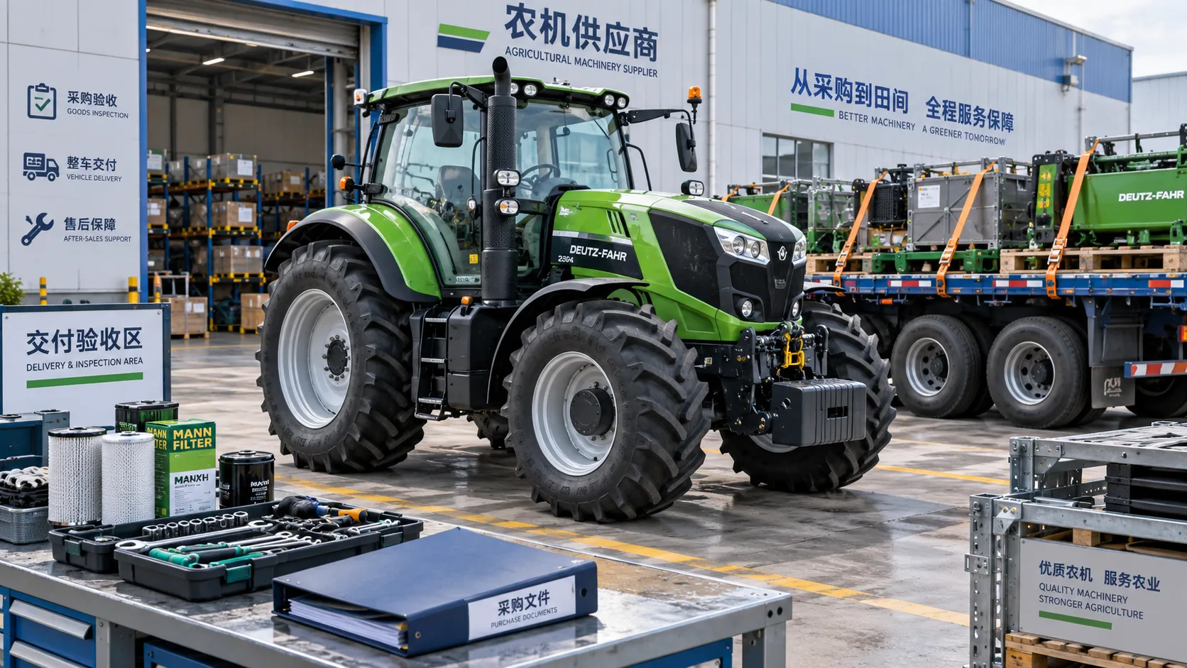
Comparing Farm Equipment Supplier Quotes: Price, Freight, and Warranty
Simplify supplier comparison for farm equipment price: assess freight, field-ready costs, and warranty coverage. Learn how to avoid hidden charges and choose a reliable supplier.
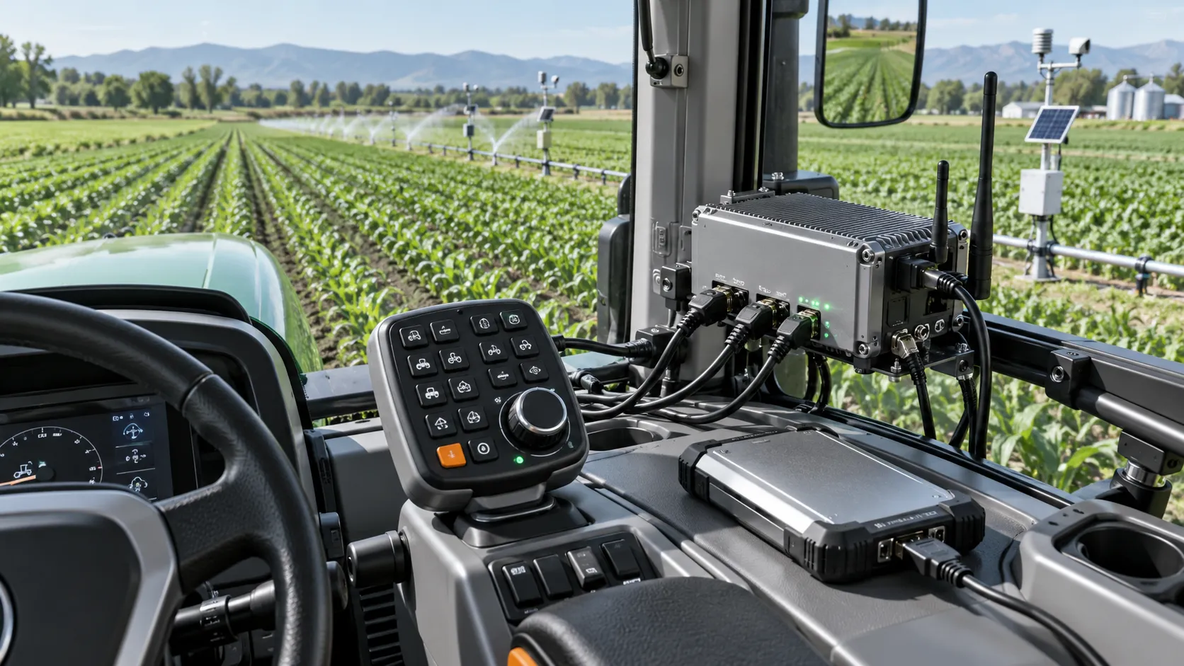
Choosing a Digital Farming Platform Provider: Compatibility and Data Ownership
Compare digital farming platforms providers on equipment compatibility, data ownership, and export rights. Discover practical checks to avoid lock-in and choose with confidence.
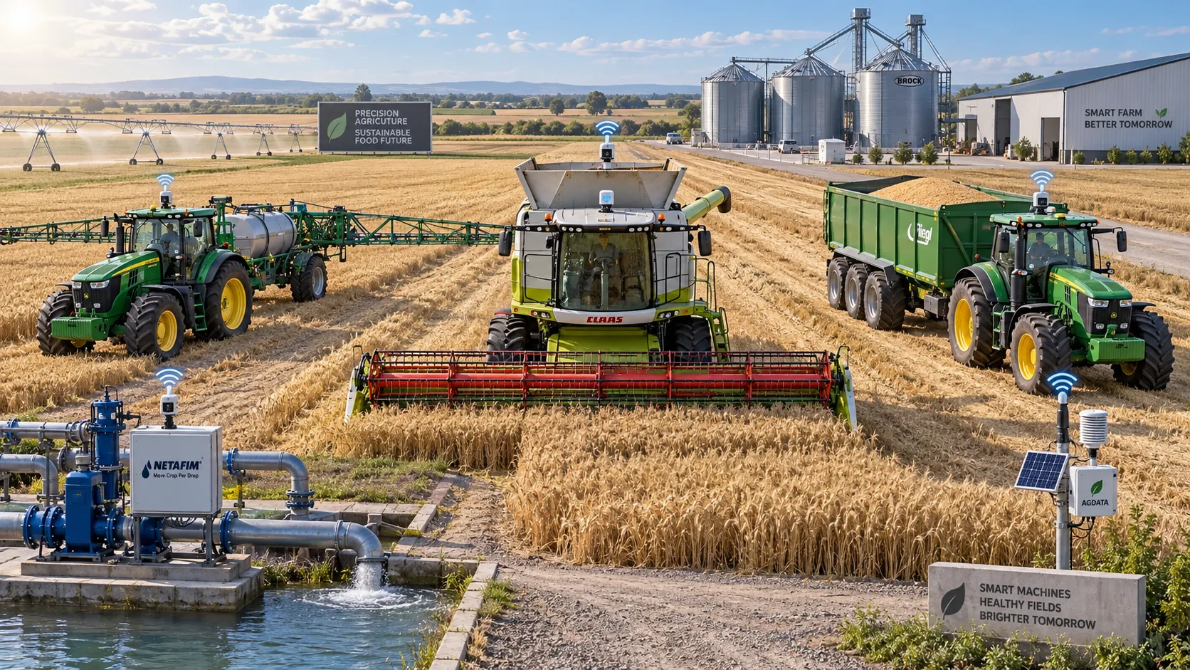
How Large-Scale Farm Telematics Cuts Downtime Across Mixed Fleets
Large-scale farm equipment telematics cuts mixed-fleet downtime with real-time alerts, smarter maintenance, and stronger operational control. Learn how to protect critical farm workflows.
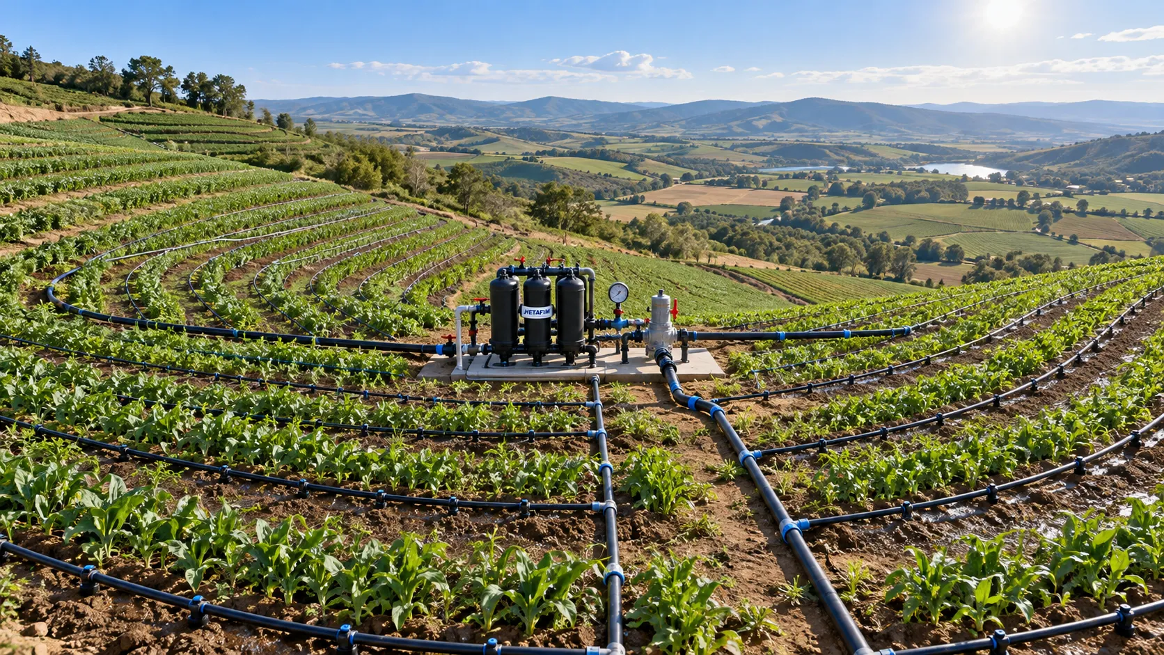
How to Size Low-Pressure Water-Saving Irrigation Systems for Uneven Fields
Low pressure water-saving irrigation systems for uneven fields: learn zoning, pressure mapping, pipe sizing, and pump selection to improve uniformity and reduce water waste.
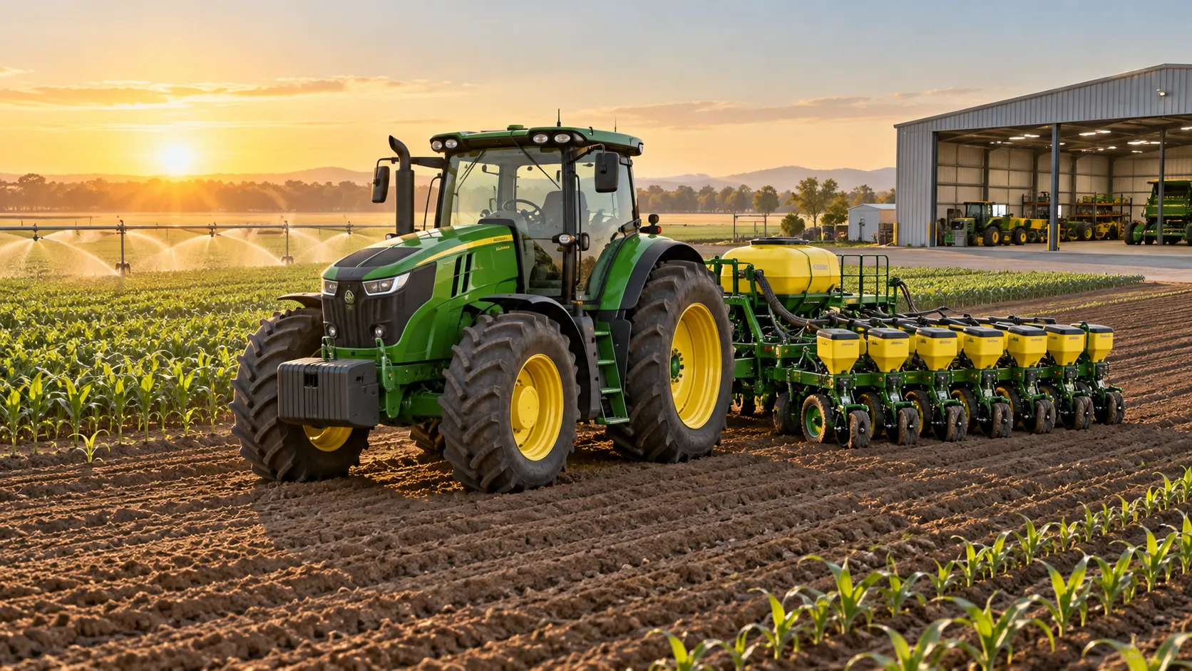
Farm Machinery Sourcing: How to Vet Suppliers, Specs, and Lifecycle Costs
Farm machinery information for sourcing: learn to vet suppliers, compare specifications, control lifecycle costs, and secure reliable uptime for smarter equipment purchases.
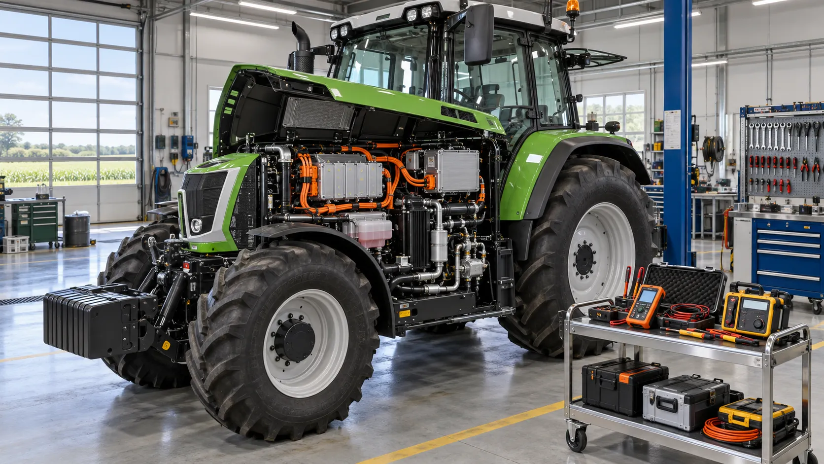
What maintenance challenges come with hybrid agricultural machines?
Hybrid agricultural machines demand smarter maintenance. Discover key challenges in high-voltage safety, batteries, software diagnostics, cooling, and parts planning.
Can hybrid propulsion systems reduce fuel use in farm machinery?
Hybrid propulsion systems for agricultural machinery can cut fuel use and boost productivity. Explore savings potential, key trade-offs, and smart investment factors.
What to compare in integrated seeding combinations for heavy soils
Compare integrated seeding combinations for heavy soils: depth control, residue flow, consolidation, traction, and field capacity for more uniform crop establishment.
When an integrated seeding combination improves field efficiency
Integrated seeding combination improves field efficiency, protects planting windows, and balances speed with seedbed quality, tractor capacity, and reliable establishment.
Related News
- 00
0000-00
Low-Pressure Drip Irrigation: How to Fix Uneven Watering Without Raising Pressure - 00
0000-00
How to Size Low-Pressure Water-Saving Irrigation Systems for Uneven Fields - 00
0000-00
Drip vs. Micro-Sprinkler Irrigation: Which System Fits Your Orchard? - 00
0000-00
How to Select Smart Irrigation Valves for Multi-Zone Water Management? - 00
0000-00
Automated Water-Saving Irrigation: How to Cut Water Use Without Reducing Crop Yields
Popular Tags
Hydrological Resource Strategist
Weekly Insights
Stay ahead with our curated technology reports delivered every Monday.