How to Size Low-Pressure Water-Saving Irrigation Systems for Uneven Fields
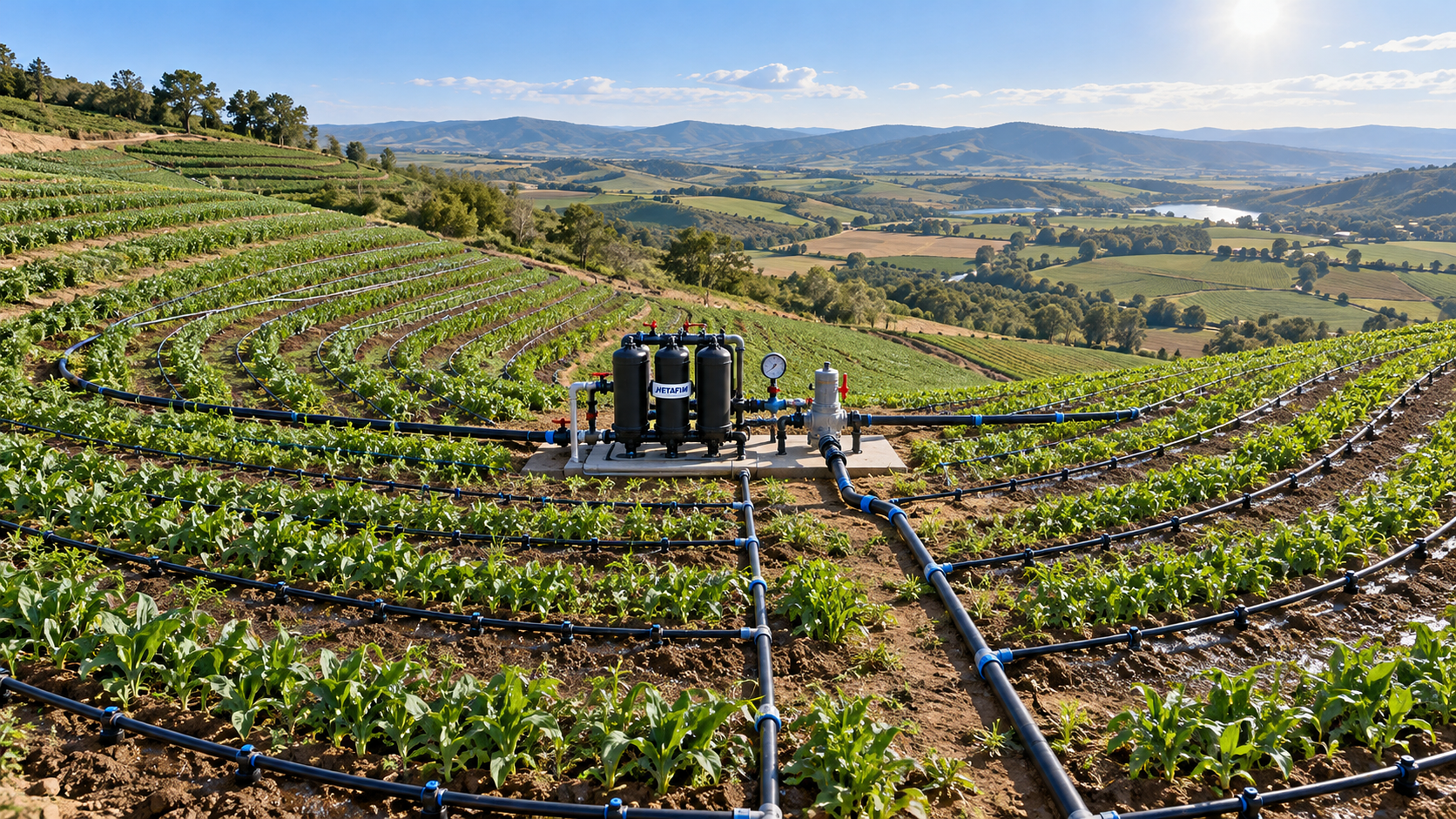




On an uneven field, an irrigation layout that appears adequate on a flat drawing can fail as soon as water reaches the higher laterals and lower blocks. Emitters near a crest may discharge too little, while those at the bottom of a slope run harder than intended. The result is not simply uneven crop growth: it can mean runoff at low points, dry root zones uphill, excessive pumping time, and repeated adjustments during the season.
The practical answer is to size low pressure water-saving irrigation systems from the field’s pressure profile rather than from total acreage alone. Start with a topographic survey, establish the allowable pressure range at each emitter or sprinkler, calculate friction and elevation effects along every hydraulic path, and divide the field into zones that can operate within that range. Pipe diameter, emitter selection, filtration, valve placement, and pump duty should all follow that sequence.
Begin with the pressure window, not the pipe catalogue
Low-pressure irrigation is often selected to reduce energy use and allow smaller pumping equipment. That benefit disappears when the system is undersized or when a layout treats a rolling field as one flat zone. Every water-delivery device has an operating range. Drip emitters, low-pressure sprinklers, micro-sprayers, and pressure-compensating devices do not respond in the same way to pressure changes, so the first engineering decision is to define what pressure variation the chosen device can tolerate while still delivering acceptable distribution uniformity.
For a non-pressure-compensating emitter, discharge changes as pressure changes. A useful relationship is:
q = kPx
where q is emitter discharge, P is pressure, k is a device-specific coefficient, and x depends on the emitter’s flow path. The equation is not a substitute for manufacturer performance data, but it explains why a seemingly modest elevation change can alter application rates across a field.
Pressure-compensating emitters can reduce the effect of terrain, but they do not remove the need for hydraulic sizing. They only compensate within their specified inlet-pressure range. If pressure at the high end of a lateral falls below the compensation threshold, discharge drops. If pressure at the low end exceeds the permitted range, fittings, tape, valves, and emitters may be exposed to unnecessary stress.
Before selecting pipe sizes, document these device limits:
- Nominal flow per emitter, sprinkler, or outlet.
- Minimum operating pressure needed for the intended discharge pattern.
- Maximum recommended operating pressure.
- Pressure-compensation range, where applicable.
- Required filtration level and sensitivity to sediment or organic debris.
- Allowable lateral length under the proposed outlet spacing and terrain condition.
This creates a pressure window. The entire design task is then to ensure that the pressure at every critical outlet remains inside that window during normal operation, including the zone farthest from the pump and the zone located at the lowest elevation.
Turn the field survey into a hydraulic map
A contour map is more useful for irrigation sizing than a single statement such as “the field slopes toward the south.” The design team needs elevations at the water source, pump location, mainline route, submain connections, control valves, lateral inlets, and representative endpoints. Sharp terraces, ridges, drainage swales, and local depressions deserve particular attention because they can create pressure changes that a broad average slope hides.
Elevation head is direct: a higher outlet receives less pressure than a lower outlet, all else being equal. In metric terms, each metre of elevation difference corresponds to roughly 0.1 bar of pressure change. The exact conversion is less important than consistently including elevation head in the calculations. On a long lateral, elevation loss and pipe friction may either compound one another or partially offset each other. A line running uphill away from the supply suffers both friction loss and elevation loss. A line descending away from the supply loses pressure to friction but gains pressure from gravity.
That distinction changes the preferred layout. A downhill lateral may seem hydraulically forgiving at its end because gravity restores pressure, yet it can produce excessive pressure at lower outlets. An uphill lateral may require shorter runs, a larger diameter, or a higher inlet pressure. A field with alternating rises and dips cannot be judged by its average grade; calculate the pressure at the local high and low points.
Identify the critical paths
For each proposed operating zone, trace at least three paths from the source to an outlet:
- The hydraulically remote high point, where elevation and friction often combine to produce the lowest residual pressure.
- The hydraulically remote low point, where elevation gain can push pressure above the device’s preferred range.
- A path with the highest expected flow, often near the beginning of a manifold or submain where many downstream outlets are operating.
The path with the longest physical distance is not automatically the limiting path. A shorter route climbing to a ridge can require more pressure than a longer route across level ground. Likewise, a lower block may not need a larger pump; it may need separation from the upper block, pressure regulation, or a different valve strategy.
Calculate flow before sizing mains and laterals
System flow is built from the outlets that run at the same time. Determine the number of emitters or sprinklers in each zone, multiply by nominal discharge, and include any required flushing flow. Do not calculate total field flow unless the whole field will genuinely operate as one zone. For uneven terrain, it often should not.
At this stage, distinguish between three flows:
A lateral does not carry the same flow along its full length because water exits through each outlet. A mainline may carry the combined demand of several zones upstream of the control valves but only one zone downstream. This is why pipe sizing should be based on segmented flow calculations instead of applying one diameter to every line.
Where the design includes different crops, row spacings, or irrigation methods, avoid combining their outlet requirements casually in one zone. A block with dense emitter spacing may require a very different flow and pressure regime than a block using wider-spaced low-pressure sprinklers. Hydraulic compatibility matters as much as physical proximity.
Use zoning to control terrain rather than overpower it
When elevation differences are substantial, the most reliable solution is usually not a larger pump. Raising source pressure enough to serve the highest point can overpressurize lower ground, increase leakage risk, and consume more energy. Zoning separates incompatible pressure conditions so that each valve set operates with a manageable elevation range.
Good zone boundaries often follow contours or divide the field into elevation bands. This is not a rigid rule. Soil type, crop blocks, irrigation scheduling, available valve locations, and access routes also affect the layout. Still, contour-based zoning is a strong starting point because outlets at similar elevations require less pressure correction.
Consider splitting a zone when any of these conditions appear during calculation:
- The difference between the highest and lowest outlet elevation uses too much of the device’s allowable pressure range.
- The residual pressure at the uphill end approaches the minimum operating limit after friction losses are included.
- The downhill section requires pressure reduction that would compromise the uphill section.
- Lateral lengths become excessive because the design is trying to reach across multiple terrain changes from one feed point.
- Soil intake rates differ enough that one runtime would lead to ponding in one area and inadequate wetting in another.
Smaller zones add valves, controls, and operating complexity, so they should not be created automatically. The decision is justified when they prevent a persistent pressure conflict. A well-zoned system may have more control points but can use more moderate pipe sizes and lower source pressure than a single oversized zone.
Match control components to the pressure profile
Pressure regulators should be located where they protect the relevant hydraulic section. A regulator at the pump outlet may control the general supply pressure but cannot correct pressure differences created farther downhill. Zone-level regulation is often more useful where blocks sit at different elevations. On long descending laterals, pressure-regulating valves or pressure-compensating emitters may be needed depending on the available pressure range and the intended application uniformity.
Air and vacuum relief also matter on irregular land. High points can trap air during filling, reducing effective flow and causing erratic outlet performance. Low points may retain water and sediment after shutdown. Install air-release devices at genuine hydraulic high points, not merely at locations that appear high from a road or field edge. Provide suitable flushing arrangements at lateral and manifold ends so sediment is not allowed to accumulate in dead-end sections.
Size pipe using both friction loss and field operations
Pipe sizing is a balance. Smaller pipe reduces initial material cost but increases friction loss, raises the pressure required at the source, and narrows the margin available for terrain changes. Larger pipe lowers friction loss and can improve control across an uneven zone, but it adds cost and may be unnecessary where flows are low or lines are short.
Use an accepted friction-loss method appropriate for the pipe material and flow regime, and use the internal diameter rather than nominal size. Hazen-Williams or Darcy-Weisbach calculations are commonly used, but consistency is more important than mixing methods. Include fittings, filters, backflow equipment, meters, valves, pressure regulators, and elevation changes. Minor losses may be small individually, yet a compact headworks assembly with several fittings can consume meaningful pressure in a low-pressure design.
For laterals, check pressure variation from inlet to the most critical outlet, not just total friction loss. The number of outlets, outlet spacing, slope direction, and emitter type all influence the result. On rolling terrain, it may be sensible to shorten laterals, feed from the centre, use split feeds, or place manifolds so laterals follow contours rather than fall directly down a slope. Each option changes installation effort, flushing arrangement, and control logic, so compare them against the pressure map rather than choosing by habit.
Pipe routing should also respect field operations. A hydraulically ideal route that crosses turning areas, drainage paths, or equipment lanes may be difficult to protect and maintain. Burial depth, crossings, isolation valves, and access to filters and flush points should be considered before finalizing the network. Changes made during installation can alter pipe lengths and elevations enough to invalidate a close hydraulic margin.
Do not treat water source capacity as a separate issue
A design can meet outlet-pressure calculations and still fail operationally if the source cannot provide the required flow at the required total dynamic head. The pump duty point must account for zone flow, static lift, elevation to the critical outlet, friction through the intake and distribution network, filtration losses, and the pressure needed at the control point.
Water quality also affects sizing. A filter that is clean has one pressure loss; a filter carrying normal sediment load has more. The design should leave operating margin for routine fouling without allowing the highest zone to drop below its required pressure. Filter selection must be tied to emitter passage size and water source characteristics. A low-pressure system with marginal filtration frequently presents as a terrain problem because the uphill rows show the first visible deficit, even though the underlying cause is pressure loss through a loaded filter.
Where supply flow is limited, increase the number of irrigation sets rather than forcing an oversized zone through an undersized source. Longer daily operating windows may be operationally acceptable; chronic low pressure is not. The scheduling plan should state which zones can run simultaneously, which must run separately, and whether flushing or filter backwashing temporarily limits available flow.
Field verification should test the design at its weak points
Commissioning is where assumptions about actual elevations, pipe installation, valve settings, and source performance are checked. Measure pressure at the zone inlet and at representative high, low, near, and far outlets while the zone is operating under normal conditions. Measure discharge where practical, especially for non-pressure-compensating outlets. A pressure gauge at only the pump tells little about what is happening at the far end of a slope.
Test after the filter has operated long enough to represent realistic conditions, not only immediately after cleaning. Observe the system during filling and shutdown as well. Surging, delayed water delivery, or visible drainage from low areas can indicate trapped air, inadequate air relief, or poor drainage arrangement.
When measured pressures differ from calculations, work from the source outward. Confirm pump output, water level, filter differential pressure, valve position, regulator setting, pipe diameter, and actual zone configuration before redesigning the entire system. Then compare surveyed and installed elevations, inspect for partially closed valves or crushed pipe, and verify that no additional rows or outlets were added to the zone after design.
Selection decisions that reduce redesign risk
For relatively gentle terrain with short laterals, standard emitters and carefully sized pipe may be enough. As elevation variation grows, pressure-compensating emitters become more attractive, particularly when lateral routing cannot follow contours. They should be selected for a verified pressure range, not simply because the label says “compensating.”
For fields with distinct upper and lower terraces, separate zones with independent regulation are usually easier to manage than attempting one common pressure. Where the field contains frequent small undulations rather than one clear slope, shorter lateral runs and strategically placed manifolds can provide more stable results than a single long header feeding every row.
The final design package should show zone boundaries, design flows, source pressure requirement, critical elevation points, pipe diameters, valve and regulator locations, filtration losses, flushing provisions, and the assumed emitter operating range. That record gives the installation team a basis for checking changes in the field and gives operators a practical reference when uneven application appears later in the season.
Related News
Farm Machinery Sourcing: How to Vet Suppliers, Specs, and Lifecycle Costs
Farm machinery information for sourcing: learn to vet suppliers, compare specifications, control lifecycle costs, and secure reliable uptime for smarter equipment purchases.
Which costs matter most when calculating precision agriculture ROI?
Calculating ROI on precision agriculture equipment? Discover the costs that shape returns, from installation and subscriptions to downtime, labor, and data integration.
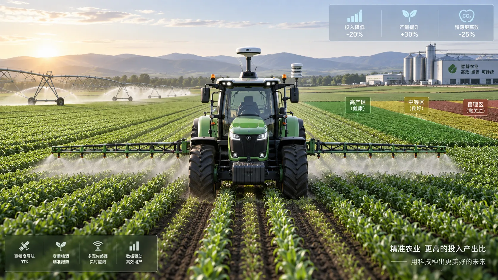
How to calculate ROI on precision agriculture equipment before buying
Calculating ROI on precision agriculture equipment: learn to assess total ownership costs, savings, payback, NPV, risks, and farm-scale value before you buy.
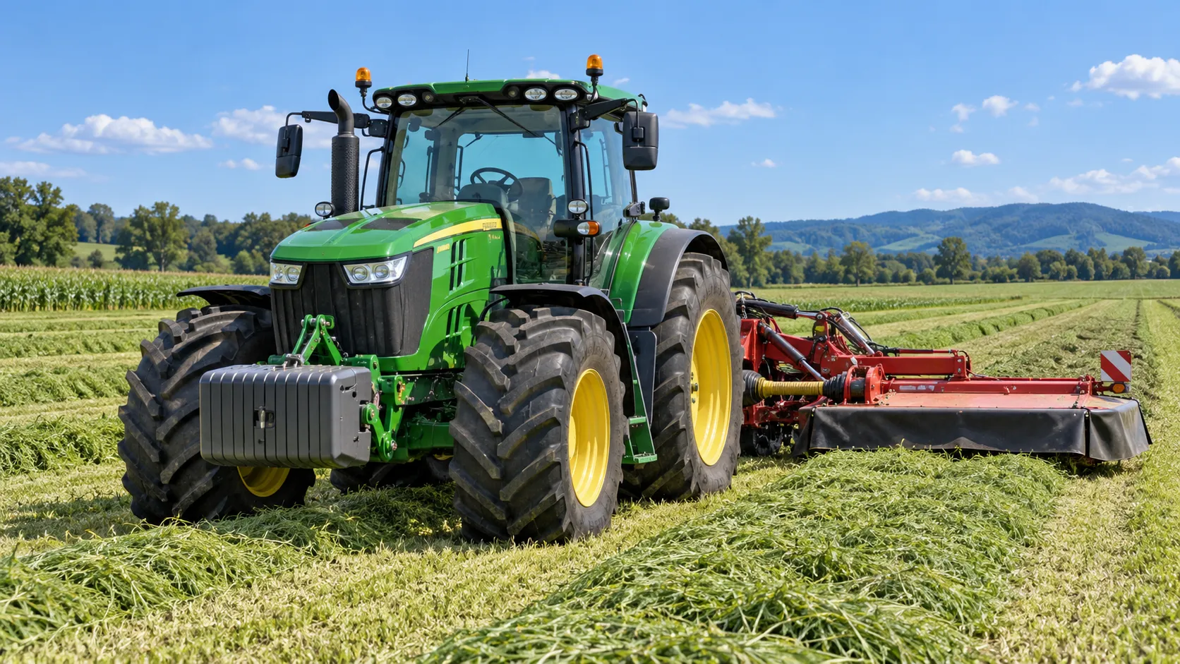
Tractor Specification Sheets: Matching PTO, Hydraulics, and Weight to Farm Tasks
Specification-oriented articles for tractors: match PTO, hydraulics, lift capacity, ballast, and weight to real farm tasks for safer, more efficient equipment choices.
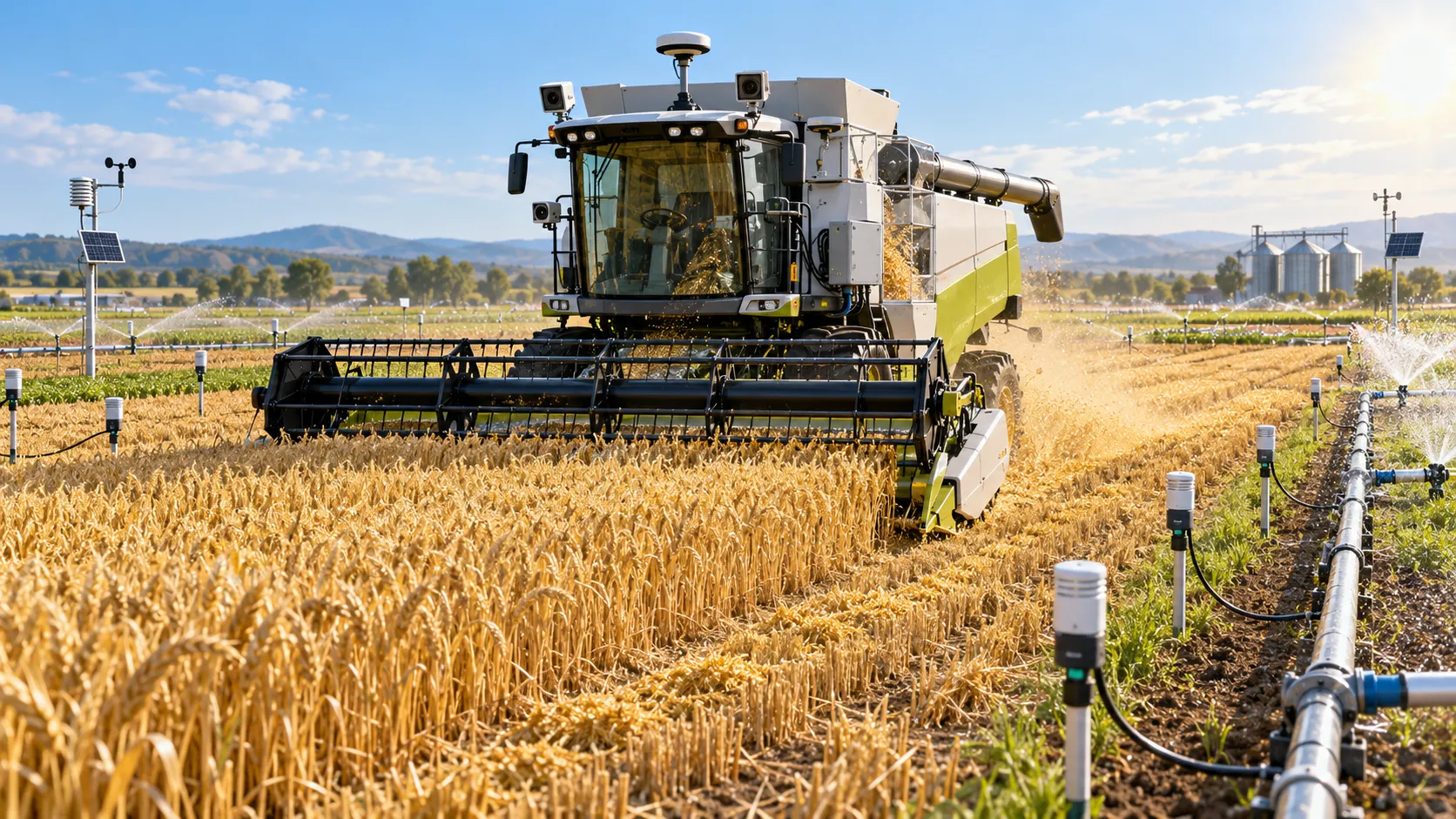
How to Evaluate Dynamic Feedback Algorithm Suppliers for Precision Farming Systems
Dynamic feedback algorithms supplier evaluation guide for precision farming—compare validation, integration, safety, and pilots to choose with confidence.
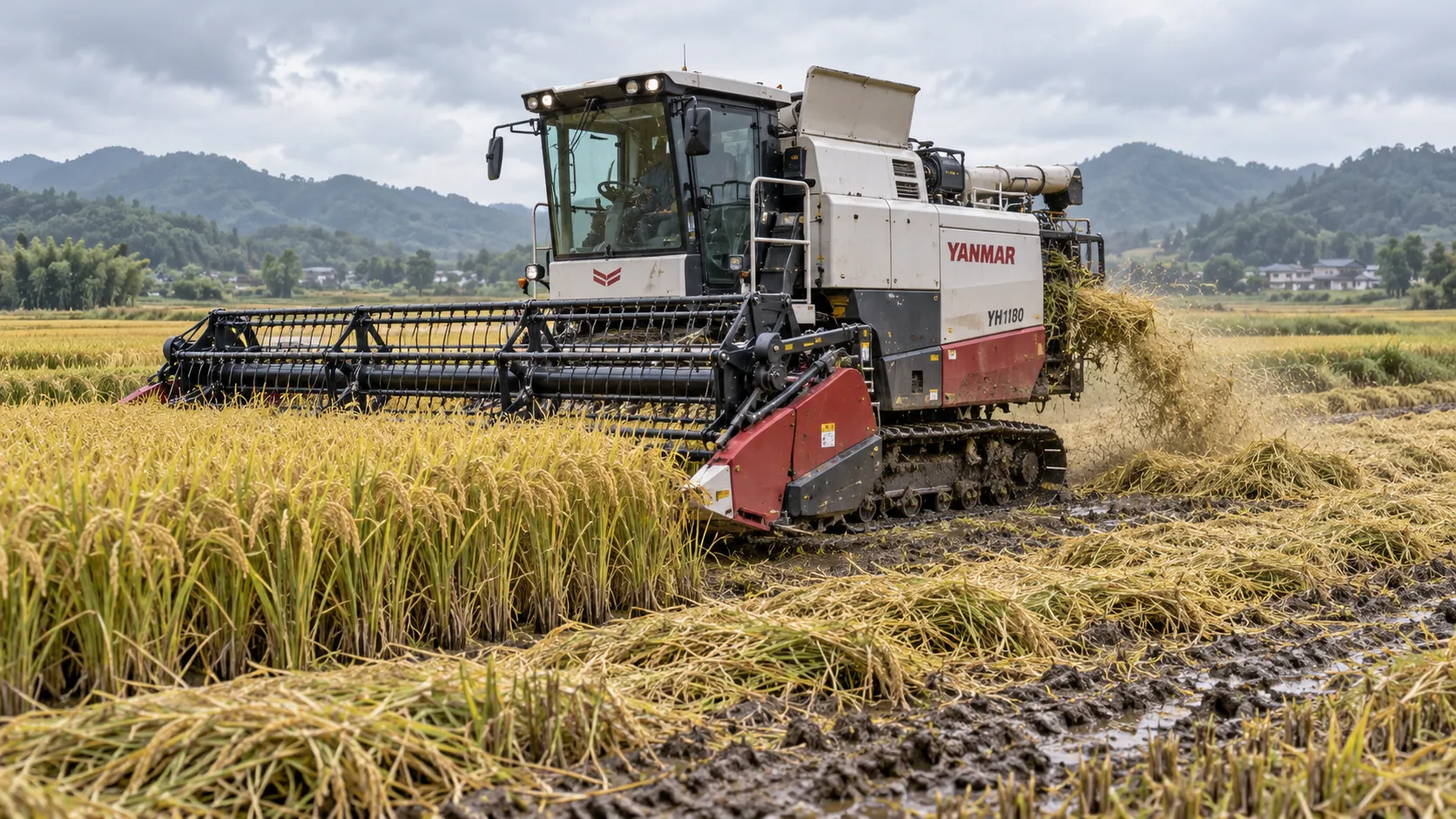
How to Specify Combine Harvester Systems for High-Moisture Grain and Variable Field Conditions
Combine harvester systems for high-moisture grain: learn how to specify threshing, cleaning, headers, traction, and automation for reliable harvests in variable fields.
How to Compare Agricultural Equipment Platforms for Fleet Management and ROI
Agricultural equipment platform comparison: evaluate fleet data, maintenance, precision workflows, and ROI to choose a system that delivers measurable results.
Drip vs. Micro-Sprinkler Irrigation: Which System Fits Your Orchard?
Irrigation solution comparison for orchards: discover whether drip or micro-sprinklers best match your water, soil, roots, fertigation, and frost needs.
Orchard Water Management: Using Soil Moisture Data to Schedule Irrigation
Agricultural water management for orchards made practical: use soil moisture data to optimize irrigation timing, protect yield, reduce costs, and improve resilience.
Related News
- 00
0000-00
How to Size Low-Pressure Water-Saving Irrigation Systems for Uneven Fields - 00
0000-00
Drip vs. Micro-Sprinkler Irrigation: Which System Fits Your Orchard? - 00
0000-00
How to Select Smart Irrigation Valves for Multi-Zone Water Management? - 00
0000-00
Automated Water-Saving Irrigation: How to Cut Water Use Without Reducing Crop Yields - 00
0000-00
How to Evaluate Drip Irrigation System Manufacturers for Large Farm Projects
Popular Tags
Hydrological Resource Strategist
Weekly Insights
Stay ahead with our curated technology reports delivered every Monday.