Tractor Specification Sheets: Matching PTO, Hydraulics, and Weight to Farm Tasks
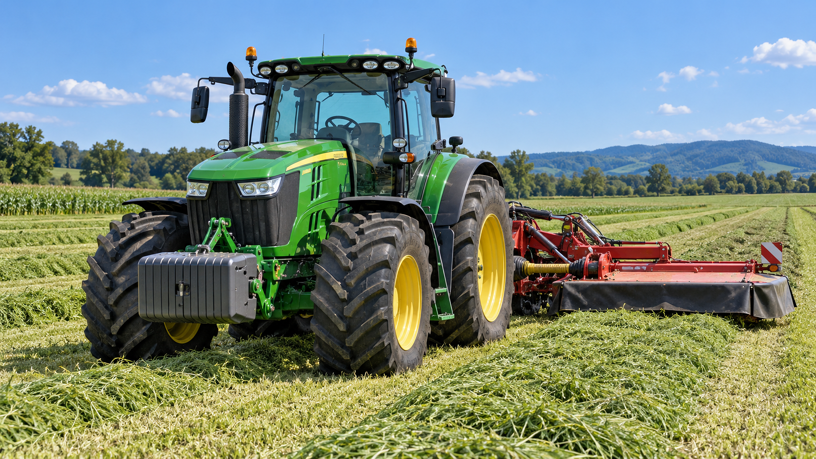




A tractor can appear adequate on paper because its engine horsepower matches the implement brochure, yet still fail to perform efficiently once the work begins. The usual symptoms are familiar: a PTO-driven mower slows in heavy material, a loader cycle becomes unresponsive when steering is used, a mounted drill cannot be lifted safely at the headland, or traction disappears after a larger implement is attached. These are not separate selection problems. They are usually the result of reading one headline specification while overlooking the relationship between PTO power, hydraulic capacity, tractor weight, ballast, and the actual duty cycle.
The practical rule is to size the tractor around the most demanding simultaneous load, not around nominal engine output. A suitable machine must deliver enough PTO power at the required speed, hydraulic flow and pressure for active functions, lift capacity at the implement’s real center of gravity, and sufficient operating mass to transfer power without compromising steering or stability. Well-built specification-oriented articles for tractors should make those connections visible before a machine reaches the field.
Start with the task, not the horsepower figure
Before comparing tractor sheets, define what the tractor will do during its busiest and most demanding period. A machine used mainly for light transport may tolerate a different specification balance than one expected to operate a front loader, a vacuum planter, and a PTO-driven forage implement in the same season.
Break each expected task into its actual loads:
- Draft load: pulling a cultivator, plow, subsoiler, disc harrow, or heavy trailer over varying soil conditions.
- PTO load: powering mowers, balers, spreaders, augers, chippers, feed mixers, or harvesting attachments.
- Hydraulic load: raising mounted equipment, operating loader cylinders, driving hydraulic motors, folding wings, or controlling hydraulic downforce.
- Stability load: carrying raised or front-mounted implements, working on slopes, handling palletized materials, or transporting a loaded implement.
- Control load: supporting guidance, section control, electric drives, sensor systems, and multiple remote-valve functions.
One implement may create several loads at once. A front loader handling a heavy bucket requires hydraulic response, front-axle capacity, rear ballast, and adequate tire contact. A large mounted planter may need lift capacity, multiple hydraulic circuits, electrical power, and stable road handling. A tractor selected only from an engine-horsepower category can be mismatched even when the engine itself is capable.
PTO ratings: use delivered power, rated speed, and load character
Engine power and PTO power are not interchangeable. PTO output reflects power available after drivetrain losses and is the more relevant figure for mechanically driven implements. When an implement manufacturer states a minimum power requirement, confirm whether that requirement refers to engine horsepower, PTO horsepower, or another unit. Treat an unspecified rating as incomplete rather than assuming it matches the tractor’s advertised engine output.
Then verify the PTO configuration. The common question is not simply whether the tractor has a rear PTO, but whether it provides the required speed and can maintain it under realistic engine operating conditions. A 540 rpm implement and a 1,000 rpm implement require compatible shafts and operating ranges. Economy PTO modes can be useful for light loads, but they should not be assumed suitable for full-load applications where the implement depends on stable shaft speed.
PTO demand also changes with crop density, moisture, material flow, cutting width, and ground speed. A mower-conditioner may operate smoothly in a thin crop and become power-limited in a dense or lodged area. A baler experiences cyclic loads rather than a perfectly steady demand. A feed mixer may impose high starting torque. In such cases, modest reserve PTO power helps the operator maintain working speed without repeatedly reducing travel speed or running the engine at an unsuitable point.
Do not solve every PTO uncertainty by selecting the highest possible power rating. Extra PTO power without sufficient machine weight can lead to wheel slip during traction-intensive work. Extra power without cooling capacity or adequate transmission suitability can also create an operational mismatch. The tractor must be able to transmit and use the power available.
Questions that reveal a PTO mismatch
- Is the implement requirement stated at the PTO or at the engine?
- Does the tractor offer the needed PTO speed as a standard operating mode?
- Will the task involve sustained high load, sharp peak loads, or mostly light running?
- Can the selected transmission hold an appropriate ground speed while engine speed remains in the PTO operating range?
- Will additional hydraulic or electrical functions operate while the PTO is under load?
Hydraulics: flow alone does not describe usable capacity
Hydraulic specifications are often reduced to one number, usually pump flow. That is useful, but it does not by itself tell you how the tractor will behave with a demanding implement. First identify whether the listed flow is total pump output, flow available to remote valves, or combined steering and implement capacity. A specification sheet may list separate steering and implement pumps, or it may list a shared system. The distinction matters when steering, loader functions, remote cylinders, and hydraulic motors are active together.
For cylinder-driven equipment, flow determines how quickly the cylinder moves, while system pressure influences the force available. A loader may lift an empty bucket quickly but struggle with a dense material load if relief pressure, geometry, or hydraulic force is limiting. For hydraulic motors, both flow and pressure must support the motor’s required speed and torque. A motor-driven air seeder, conveyor, or precision metering system can be sensitive to inconsistent oil supply.
Remote valve count is another overlooked restriction. Count the functions that must be connected at the same time, not merely the implement’s total cylinder count. A fold-and-lift implement may need separate circuits for lift, fold, marker control, hydraulic downforce, or auxiliary drive. Check whether valves are standard, whether they are mechanically or electronically controlled, and whether any circuit offers the flow adjustment or detent function needed by a hydraulic motor.
A further point is hydraulic oil management. High continuous demand produces heat. A tractor that handles occasional cylinder movement may not be configured for long periods of hydraulic-motor operation. Review cooling provision, permitted continuous flow, recommended return arrangement, and implement instructions before treating a remote valve as a universal power source.
Lift capacity must be read at the correct distance
Three-point hitch lift capacity is one of the easiest figures to misread. Manufacturers may state maximum lift at the hitch points, at a specified distance behind them, or under a particular test arrangement. A mounted implement does not place its mass directly at the lift points. Its center of gravity sits behind the tractor, and that distance creates leverage against the hitch.
A tractor may therefore lift a nominally heavy attachment close to the linkage but have little reserve with a long-frame drill, rear tank, toolbar, or folding mower combination. The problem becomes more severe when the implement is raised for turning or road transport, because dynamic movement, uneven ground, and slope alter the load transferred to the tractor.
When comparing lift figures, document the implement’s operating mass, any carried seed, fertilizer, water, or crop material, and the distance from the hitch points to the loaded center of gravity. Add mounted accessories that remain on the machine during operation. Then compare this real configuration with the tractor’s rating at the closest stated measurement distance. A large headline lift number without a stated measurement point should be treated cautiously.
Lift capacity is also different from front-end stability. A rear implement can be lifted hydraulically while still reducing steering authority by unloading the front axle. Front weights may restore balance, but they add axle load and must remain within the tractor’s approved limits. For machines carrying front and rear equipment together, evaluate both axles, not only the rear hitch.
Weight, ballast, tires, and traction form one system
Operating weight affects pulling ability, braking stability, ride, compaction, and implement control. A lighter tractor may be easier to transport and may cause less soil loading in some conditions, but it cannot automatically use all of its available power in draft work. When tire grip is inadequate, engine power is converted into wheel slip rather than useful drawbar work.
Ballast is not simply added mass. It is a way to place enough load on the correct axle for the task. Loader work often calls for rear ballast to counterbalance the front load and preserve rear-tire contact. Heavy rear-mounted implements can require front ballast to maintain steering control. Drawbar work may benefit from a different distribution than transport or loader operation. Fixed weights, wheel weights, liquid ballast, and removable front packages all affect handling differently.
Use the tractor’s unballasted weight as a starting point, then assess the actual operating configuration: loader fitted or removed, front linkage present, rear implement raised, dual wheels installed, tire size selected, and any front or rear weights attached. The brochure shipping weight may exclude fluids, ballast, cab options, loader frames, and tires. It is not necessarily the field-ready mass.
Tire selection can change the result as much as a modest power increase. Tire dimensions, construction, inflation pressure, and field conditions influence the contact patch and the load each tire can carry. A tractor intended for heavy draft work on soft ground may need a different tire strategy from one spending much of its time on firm yards and roads. Do not add ballast without considering allowable tire loads, axle ratings, soil conditions, and road speed.
Where weight problems usually show up
Excessive slip during tillage indicates that the tractor cannot convert power into pull efficiently, though implement depth and soil condition should also be checked. Light or wandering steering with a raised rear implement points to inadequate front-axle loading. A loader that feels unstable over uneven ground may have insufficient rear counterweight, inappropriate tire pressure, or a load outside practical handling limits. Poor braking behavior on a slope is not solved by engine power; it is a mass distribution, axle-load, tire, and operating-practice issue.
Check the transmission and chassis before approving the match
PTO, hydraulics, and weight cannot be assessed in isolation from the drivetrain. A tractor used for ground-engaging work needs usable speed steps around the desired operating range. Wide gaps between ratios can force an operator to choose between excessive engine speed and an unsuitable travel speed. Continuously variable, powershift, powershuttle, and mechanical transmission designs each offer different control characteristics, but the important question is whether the chosen configuration holds the implement at its required working speed under load.
Review four-wheel-drive engagement, differential-lock operation, front-axle design, wheelbase, and turning requirements in relation to the task. A long wheelbase may improve ride and stability with large implements but can be less convenient around confined storage areas. A loader tractor needs more than a loader-compatible frame: visibility, reversing control, axle capacity, and the ability to retain stable steering with a loaded bucket all matter.
Precision equipment adds another layer. Guidance displays, implement controllers, section control, and rate systems may require suitable electrical connections, signal compatibility, mounting space, and hydraulic responsiveness. These requirements should be documented alongside mechanical specifications rather than treated as accessories to be addressed after the tractor is selected.
A practical way to compare specification sheets
Create one row for each tractor and one column for every non-negotiable requirement. Record the source and measurement condition for each value rather than copying figures without context. The resulting comparison is more useful when it distinguishes required capacity from desirable reserve.
- List the implements that create the highest PTO, hydraulic, lift, and traction demands.
- Record each implement’s required PTO speed, power basis, hydraulic functions, filled operating weight, and transport arrangement.
- Compare PTO output at rated speed, not just maximum engine output.
- Separate hydraulic flow available to implement circuits from steering or combined pump figures.
- Check rear-hitch capacity at a stated distance and calculate whether the loaded implement places its center of mass farther rearward.
- Estimate field-ready tractor mass and axle loading with the expected loader, front weights, rear ballast, and tires.
- Confirm that transmission ratios, remote valves, electrical connections, and axle ratings support the full operating configuration.
When a specification remains ambiguous, request the detailed operator documentation or a manufacturer clarification for that exact configuration. This is especially important where hydraulic figures are expressed differently across models, where lift capacity lacks a measurement distance, or where optional pumps and axles change the available capability. A sound selection is not the tractor with the largest isolated number; it is the one whose PTO, hydraulics, lift, traction, and stability remain adequate when the real implement is loaded and working.
Related News
How to Evaluate Dynamic Feedback Algorithm Suppliers for Precision Farming Systems
Dynamic feedback algorithms supplier evaluation guide for precision farming—compare validation, integration, safety, and pilots to choose with confidence.
How to Specify Combine Harvester Systems for High-Moisture Grain and Variable Field Conditions
Combine harvester systems for high-moisture grain: learn how to specify threshing, cleaning, headers, traction, and automation for reliable harvests in variable fields.
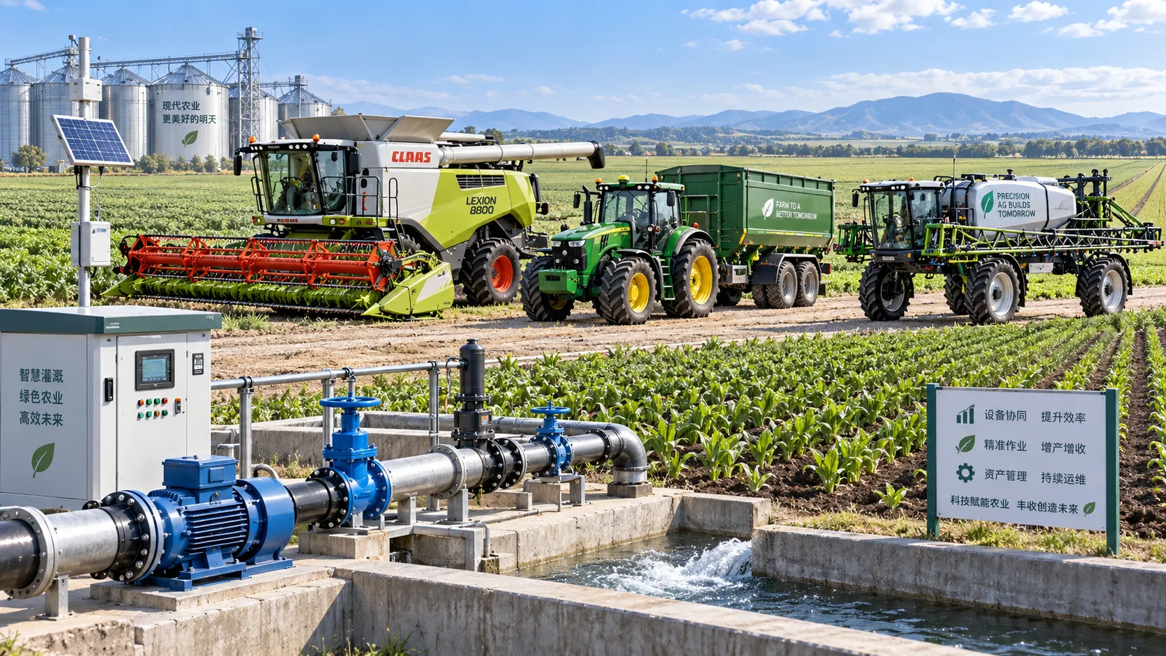
How to Compare Agricultural Equipment Platforms for Fleet Management and ROI
Agricultural equipment platform comparison: evaluate fleet data, maintenance, precision workflows, and ROI to choose a system that delivers measurable results.
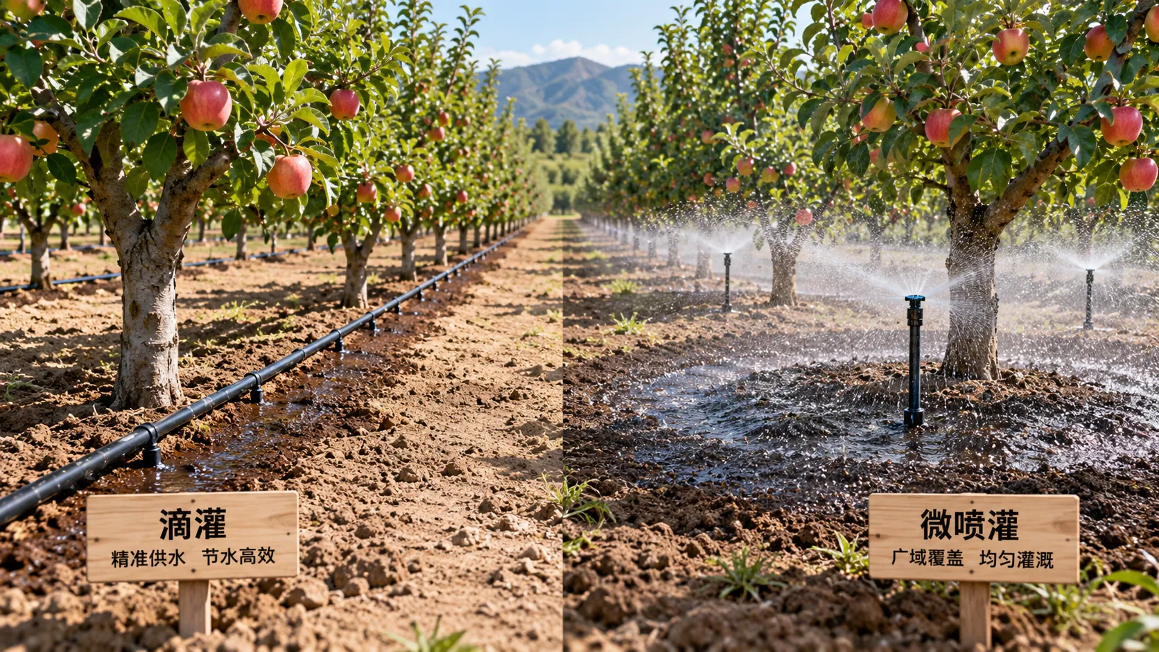
Drip vs. Micro-Sprinkler Irrigation: Which System Fits Your Orchard?
Irrigation solution comparison for orchards: discover whether drip or micro-sprinklers best match your water, soil, roots, fertigation, and frost needs.
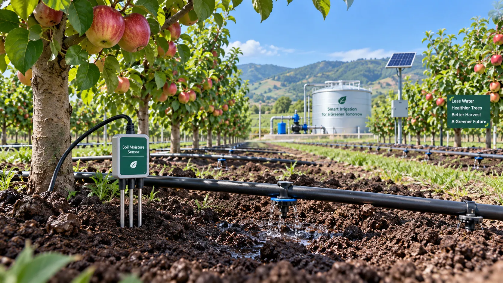
Orchard Water Management: Using Soil Moisture Data to Schedule Irrigation
Agricultural water management for orchards made practical: use soil moisture data to optimize irrigation timing, protect yield, reduce costs, and improve resilience.
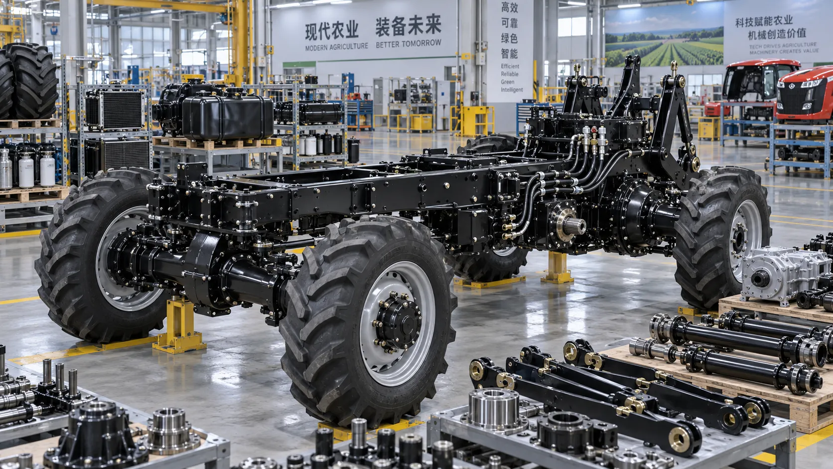
Tractor Chassis Price: What Buyers Should Compare Beyond the Initial Quote
Tractor chassis price is only the start. Compare load capacity, compatibility, durability, and lifecycle costs to choose a reliable, high-value chassis.

How to Select Smart Irrigation Valves for Multi-Zone Water Management?
Intelligent irrigation systems valves: learn how to match smart valves with multi-zone flow, pressure, control, feedback, and communication needs for reliable water management.
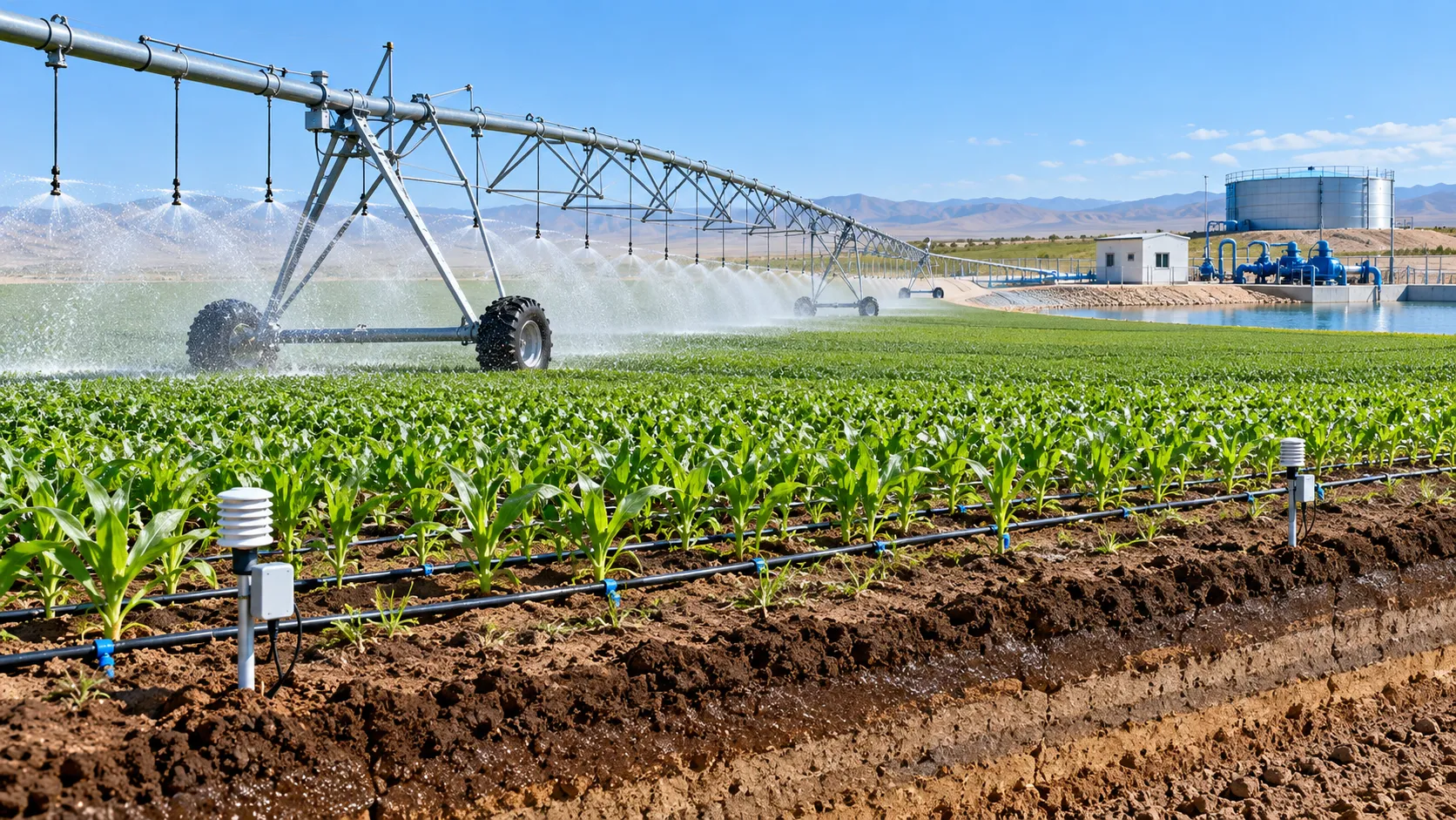
Climate-Smart Farming for Drought: A Practical Plan for Protecting Yields
Climate-smart farming for drought: build smarter water budgets, protect critical crop stages, improve irrigation uniformity, and safeguard yields with practical field-proven strategies.
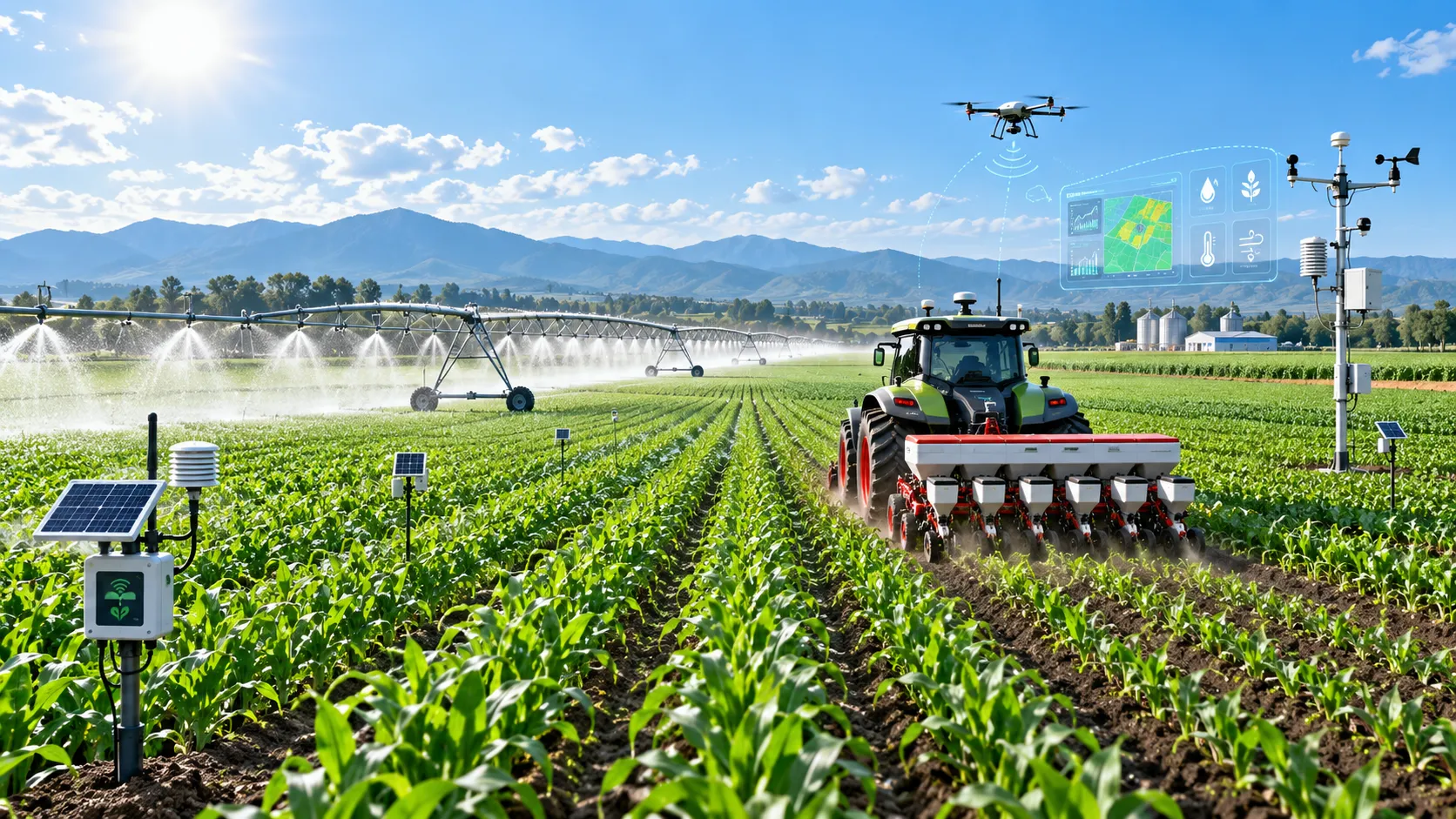
How Digital Agriculture Platforms Turn Field Data Into Better Input Decisions
Digital agriculture platforms turn field data into smarter fertilizer, water, seed, and equipment decisions—helping farms cut risk, improve margins, and scale sustainability.
Related News
- 00
0000-00
Tractor Specification Sheets: Matching PTO, Hydraulics, and Weight to Farm Tasks - 00
0000-00
How to Compare Agricultural Equipment Platforms for Fleet Management and ROI - 00
0000-00
Tractor Chassis Price: What Buyers Should Compare Beyond the Initial Quote - 00
0000-00
How Digital Agriculture Platforms Turn Field Data Into Better Input Decisions - 00
0000-00
When Does Agricultural Machinery Leasing Cost Less Than Owning Equipment?
Popular Tags
Ms. Elena Rodriguez
Weekly Insights
Stay ahead with our curated technology reports delivered every Monday.